| Oracle Fusion Middleware Developer's Guide for Oracle TopLink 11g Release 1 (11.1.1) Part Number B32441-03 |
|
|
View PDF |
| Oracle Fusion Middleware Developer's Guide for Oracle TopLink 11g Release 1 (11.1.1) Part Number B32441-03 |
|
|
View PDF |
This chapter describes how to configure a TopLink coordinated cache.
This chapter includes the following sections:
For more information, see Section 102.3, "Cache Coordination".
Table 103-1 lists the configurable options shared by two or more TopLink coordinated cache types. In addition to the configurable options described here, you must also configure the options described for the specific Coordinated Cache Types, as shown in Table 103-2.
Table 103-2 Common Coordinated Cache Options
| Option to Configure | Oracle JDeveloper |
TopLink Workbench |
Java |
|---|---|---|---|
|
Cache coordination change propagation at the descriptor level (see Section 119.15, "Configuring Cache Coordination Change Propagation at the Descriptor Level") |
|
||
|
Synchronous change propagation mode (see Section 103.2, "Configuring the Synchronous Change Propagation Mode") |
|
||
|
Service channel (see Section 103.3, "Configuring a Service Channel") |
|
||
|
Multicast group address (see Section 103.4, "Configuring a Multicast Group Address") |
|
||
|
Multicast port (see Section 103.5, "Configuring a Multicast Port") |
|
||
|
Naming service type (see Section 103.6, "Configuring a Naming Service Type") |
|
||
|
Announcement delay (see Section 103.9, "Configuring an Announcement Delay") |
|
||
|
Connection handling (see Section 103.10, "Configuring Connection Handling") |
|
||
|
Context properties (see Section 103.11, "Configuring Context Properties") |
|
||
|
Packet time-to-live (see Section 103.12, "Configuring a Packet Time-to-Live") |
|
You can configure whether the coordinated cache should propagate object changes asynchronously or synchronously.
Table 103-3 summarizes which coordinated caches support propagation mode configuration.
Table 103-3 Coordinated Cache Support for Propagation Mode Configuration
| Coordinated Cache | How to Use Oracle JDeveloper | How to Configure the Synchronous Change Propagation Mode Using TopLink Workbench |
How to Configure the Synchronous Change Propagation Mode Using Java |
|---|---|---|---|
|
JMS Coordinated Cache (asynchronous only) |
|
|
|
|
|
|
|
|
|
|
|
|
|
|
|
|
|
Synchronous propagation mode forces the session to wait for an acknowledgement before sending the next object change notification: this reduces the likelihood of stale data at the expense of performance.
Asynchronous propagation mode allows the session to create separate threads to propagate changes to remote servers. TopLink returns control to the client immediately after the local commit operation, whether or not the changes merge successfully on the remote servers. This offers superior performance for applications that are somewhat tolerant of stale data.
For more information, Section 102.2.3, "Handling Stale Data".
To specify the change propagation mode, use this procedure:
Select a session or session broker in the Navigator. Its properties appear in the Editor.
Click the Cache Coordination tab. The Cache Coordination tab appears.
Ensure the Enable Cache Coordination option is selected, then select the appropriate coordinated cache Type (see Table 103-3). The cache coordination options appear on the tab.
Figure 103-1 Cache Coordination Tab, Synchronous Field
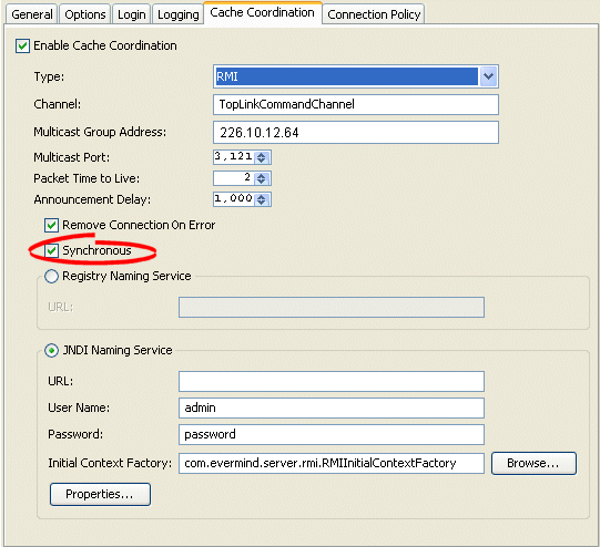
Select the Synchronous option to use synchronous change propagation. Do not select this option to use asynchronous change propagation.
Use the oracle.toplink.remotecommand.RemoteCommandManager method setShouldPropagateAsynchronously to define whether changes should be propagated synchronously or asynchronously for this coordinated cache.
For more information, see Section 102.4.4, "Cache Coordination API".
The service channel is the name of the TopLink coordinated cache channel to which sessions subscribe in order to participate in the same coordinated cache. Such sessions use the service channel to exchange messages with each other. Messages sent on other service channels will not be exchanged with this coordinated cache.
Table 103-4 summarizes which coordinated caches support service channel configuration.
Table 103-4 Coordinated Cache Support for Service Channel Configuration
| Coordinated Cache | How to Use Oracle JDeveloper | How to Configure a Service Channel Using TopLink Workbench |
How to Configure a Service Channel Using Java |
|---|---|---|---|
|
|
|
|
|
|
|
|
|
|
|
|
|
|
|
|
|
|
|
To specify the service channel, use this procedure:
Select a session or session broker in the Navigator. Its properties appear in the Editor.
Click the Cache Coordination tab. The Cache Coordination tab appears.
Ensure the Enable Cache Coordination option is selected, then select the appropriate coordinated cache Type (see Table 103-4). The cache coordination options appear on the tab.
Figure 103-2 Cache Coordination Tab, Channel Field
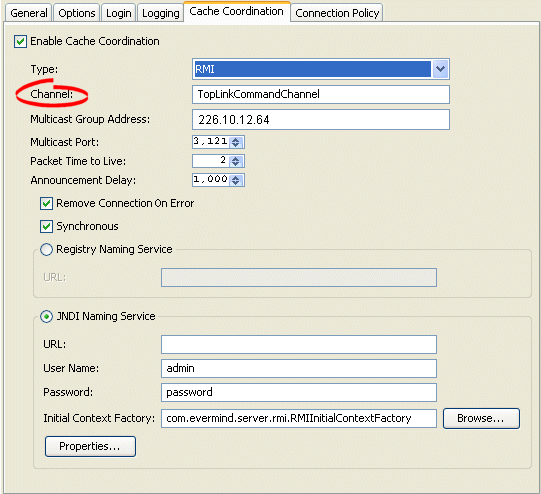
In the Channel field, enter the name of the service channel for this coordinated cache.
Use the oracle.toplink.remotecommand.RemoteCommandManager method setChannel to set the name of the service channel for this coordinated cache.
For more information, see Section 102.4.4, "Cache Coordination API".
A multicast group address is an Internet Protocol (IP) address in the range 224.0.0.0 to 239.255.255.255 that identifies the members of an IP multicast group. To efficiently broadcast the same message to all members of an IP multicast group, you configure each recipient with the same multicast group address and send the message to that address.
Table 103-5 summarizes which coordinated caches support multicast group address configuration.
Table 103-5 Coordinated Cache Support for Multicast Group Address Configuration
| Coordinated Cache | How to Use Oracle JDeveloper | How to Configure a Multicast Group Address Using TopLink Workbench |
How to Configure a Multicast Group Address Using Java |
|---|---|---|---|
|
|
|
|
|
|
|
|
|
|
|
|
|
|
|
|
|
|
|
Note:
Ensure your host and network are configured to support multicast operation before configuring this option.In addition to configuring the multicast group address, you must also configure the multicast port (see Section 103.5, "Configuring a Multicast Port") for the coordinated cache types shown in Table 103-5.
To specify the multicast group address, use this procedure:
Select a session or session broker in the Navigator. Its properties appear in the Editor.
Click the Cache Coordination tab. The Cache Coordination tab appears.
Ensure the Enable Cache Coordination option is selected, then select the appropriate coordinated cache Type (see Table 103-5). The cache coordination options appear on the tab.
Figure 103-3 Cache Coordination Tab, Multicast Group Address Field
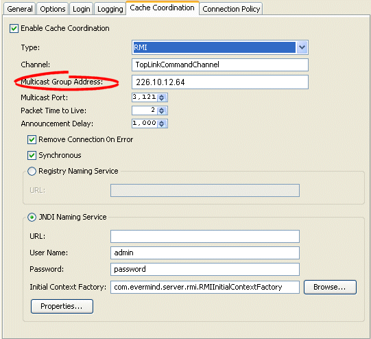
Enter the multicast group address in the range 224.0.0.0 to 239.255.255.255 to subscribe this session to a given coordinated cache.
Use the oracle.toplink.remotecommand.DiscoveryManager method setMulticastGroupAddress to subscribe this session to a given coordinated cache.
Note:
Ensure that the address falls in the range of 224.0.0.0 to 239.255.255.255For more information, see Section 102.4.4, "Cache Coordination API".
The multicast port is the port on which multicast messages are received. Members of a multicast group (see Section 103.4, "Configuring a Multicast Group Address") rely on messages broadcast to their multicast group address to communicate with one another.
Table 103-6 summarizes which coordinated caches support multicast port configuration.
Table 103-6 Coordinated Cache Support for Multicast Port Configuration
| Coordinated Cache | How to Use Oracle JDeveloper | How to Configure a Multicast Port Using TopLink Workbench |
How to Configure a Multicast Port Using Java |
|---|---|---|---|
|
|
|
|
|
|
|
|
|
|
|
|
|
|
|
|
|
|
|
Note:
Ensure your host and network are configured to support multicast operation before configuring this optionTo specify the multicast port, use this procedure:
Select a session or session broker in the Navigator. Its properties appear in the Editor.
Click the Cache Coordination tab. The Cache Coordination tab appears.
Ensure the Enable Cache Coordination option is selected, then select the appropriate coordinated cache Type (see Table 103-6). The cache coordination options appear on the tab.
Figure 103-4 Cache Coordination Tab, Multicast Port Field
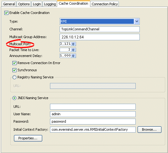
Enter the multicast port on which messages broadcast to the multicast group address are received.
Use the oracle.toplink.remotecommand.DiscoveryManager method setMulticastPort to define the multicast port on which messages broadcast to the multicast group address are to be received.
For more information, see Section 102.4.4, "Cache Coordination API".
The session's message transport service uses a naming service when it looks up connections to other sessions in the coordinated cache. You can configure the message transport service to look up remote objects using an RMI registry or Java Naming and Directory Interface (JNDI). By default, JNDI is used.
Table 103-7 summarizes which coordinated caches support naming service configuration.
Table 103-7 Coordinated Cache Support for Naming Service Configuration
| Coordinated Cache | JNDI Naming Service | RMI Registry Naming Service |
|---|---|---|
|
|
|
|
|
|
|
|
|
|
|
|
|
|
|
For information, see the following:
The session's message transport service uses a naming service when it looks up connections to other sessions in the coordinated cache. If you choose to use a JNDI naming service, you must configure JNDI naming service information.
Table 103-8 summarizes which coordinated caches support JNDI naming service configuration.
Table 103-8 Coordinated Cache Support for JNDI Naming Service Configuration
| Coordinated Cache | How to Use Oracle JDeveloper | How to Configure JNDI Naming Service Information Using TopLink Workbench |
How to Configure JNDI Naming Service Information Using Java |
|---|---|---|---|
|
|
|
|
|
|
|
|
|
|
|
|
|
|
|
|
|
|
|
TopLink uses JNDI naming service information differently, depending on the type of coordinated cache.
For a JMS coordinated cache, when a particular session's coordinated cache starts up, it uses its JNDI naming service information to locate and create a connection to the JMS server. The coordinated cache is ready when all participating sessions are connected to the JMS server. At this point, sessions can start sending and receiving object change messages. You can then configure all sessions that are participating in the same coordinated cache with the same JNDI naming service information.
For an RMI or CORBA coordinated cache, when a particular session's coordinated cache starts up, the session binds its connection in JNDI, creates an announcement message (that includes its own JNDI naming service information), and broadcasts the announcement to its multicast group (see Section 103.4, "Configuring a Multicast Group Address" and Section 103.5, "Configuring a Multicast Port"). When a session that belongs to the same multicast group receives this announcement, it uses the JNDI naming service information in the announcement message to establish bidirectional connections with the newly announced session's coordinated cache. The coordinated cache is ready when all participating sessions are interconnected in this way, at which point, sessions can start sending and receiving object change messages. You can then configure each session with JNDI naming information that identifies the host on which the session is deployed.
To specify the sessions's JNDI naming service, use this procedure:
Select a session or session broker in the Navigator. Its properties appear in the Editor.
Click the Cache Coordination tab. The Cache Coordination tab appears.
Ensure the Enable Cache Coordination option is selected, then select the appropriate coordinated cache Type (see Table 103-8). The cache coordination options appear on the tab.
Figure 103-5 Cache Coordination Tab, JNDI Naming Service Options
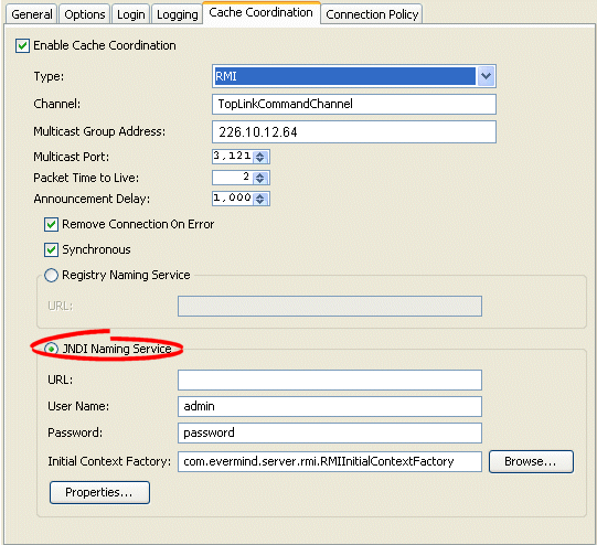
Use the following information to enter data in the fields of the Cache Coordination tab to configure the naming service options:
| Field | Description |
|---|---|
| URL | The location of the JNDI naming service.
For a JMS coordinated cache: If you are using the Oracle Containers for Java EE (OC4J) JNDI naming service and all the hosts in your coordinated cache can communicate using the OC4J proprietary RMI protocol ORMI, use a URL similar to the following: ormi://<JMS-host-IP>:<JMS-host-port> where For an RMI or CORBA coordinated cache: If you are using the OC4J JNDI naming service and all the hosts in your coordinated cache can communicate using the OC4J proprietary RMI protocol ORMI on OC4J default port 23791, use a URL similar to the following: ormi://<session-host-IP>:23791 where |
| Username | The user name required to log in to the JNDI naming service.
The value you enter defines the |
| Password | The plain text (unencrypted) password required to log in to the JNDI naming service. The password appears in plain text in TopLink Workbench, but it is encrypted when written to the sessions.xml file.
The value you enter defines the |
| Initial Context Factory | The name of the factory class, provided by your JNDI naming service provider, that implements the javax.naming.spi.InitialContextFactory interface. This factory class is used to create a javax.naming.Context instance that can access the JNDI naming service provider's context implementation.
The value you enter defines the |
| Properties | The JNDI context properties.
Click Properties to configure custom JNDI context properties (see Section 103.11, "Configuring Context Properties"). |
Use the oracle.toplink.remotecommand.TransportManager method setNamingServiceType as follows:
setNamingServiceType(TransportManager.JNDI_NAMING_SERVICE)
Then use the following TransportManager methods to configure the JNDI naming service options:
setUserName–Set the user name required to log in to the JNDI naming service. The value you enter defines the Context.SECURITY_PRINCIPAL environment property.
setPassword–Set the unencrypted password required to log in to the JNDI naming service. The value you enter defines the Context.SECURITY_CREDENTIALS in the cached context properties.
setEncriptedPassword–Set the encrypted password required to log in to the JNDI naming service. The value you enter defines the Context.SECURITY_CREDENTIALS in the cached context properties.
setInitialContextFactoryName–The name of the factory class, provided by your JNDI naming service provider, that implements the javax.naming.spi.InitialContextFactory interface. This factory class is used to create a javax.naming.Context instance that can access the JNDI naming service provider's context implementation. The value you enter defines the Context.INITIAL_CONTEXT_FACTORY in the cached context properties.
setLocalContextProperties–Set the properties that will be used to create the initial context for local JNDI access.
Do not forget to specify the location of the JNDI naming service by providing its URL. Consider the following:
For a JMS coordinated cache, if you are using the OC4J JNDI naming service and all the hosts in your coordinated cache can communicate using the OC4J proprietary RMI protocol ORMI, use a URL similar to the following:
ormi://<JMS-host-IP>:<JMS-host-port>
where JMS-host-IP is the IP address of the host on which the JMS service provider is running, and JMS-host-port is the port on which the JMS service provider is listening for JMS requests.
For an RMI or CORBA coordinated cache, if you are using the OC4J JNDI naming service and all the hosts in your coordinated cache can communicate using the OC4J proprietary RMI protocol ORMI on OC4J default port 23791, use a URL similar to the following:
ormi://<session-host-IP>:23791
where session-host-IP is the IP address of the host on which this session is deployed.
Note that the default protocol value is "ormi", and the default port value is "23791". You can also use the TransportManager.DEFAULT_URL_PROTOCOL and DEFAULT_URL_PORT.
For more information, see Section 102.4.4, "Cache Coordination API".
The session's message transport service uses a naming service when it looks up connections to other sessions in the coordinated cache. If you choose to use an RMI registry naming service, you can configure RMI registry naming service options.
Table 103-8 summarizes which coordinated caches support RMI registry naming service configuration.
Table 103-9 Coordinated Cache Support for RMI Registry Naming Service Configuration
| Coordinated Cache | How to Use Oracle JDeveloper | How to Configure RMI Registry Naming Service Information Using TopLink Workbench |
How to Configure RMI Registry Naming Service Information Using Java |
|---|---|---|---|
|
|
|
|
|
|
|
|
|
|
|
|
|
|
|
|
|
|
|
For an RMI coordinated cache, when a particular session's coordinated cache starts up, the session binds its connection in its RMI registry, creates an announcement message (that includes its own naming service information), and broadcasts the announcement to its multicast group (see Section 103.4, "Configuring a Multicast Group Address" and Section 103.5, "Configuring a Multicast Port"). When a session that belongs to the same multicast group receives this announcement, it uses the JNDI naming service information in the announcement message to establish bidirectional connections with the newly announced session's coordinated cache. The coordinated cache is ready when all participating sessions are interconnected in this way, at which point, sessions can start sending and receiving object change messages. You can then configure each session with RMI registry naming information that identifies the host on which the session is deployed.
To specify the sessions's registry naming service, use this procedure:
Select a session or session broker in the Navigator. Its properties appear in the Editor window.
Click the Cache Coordination tab. The Cache Coordination tab appears.
Ensure the Enable Cache Coordination option is selected, then select the appropriate coordinated cache Type (see Table 103-9). The cache coordination options appear on the tab.
Figure 103-6 Cache Coordination Tab, Naming Service Options
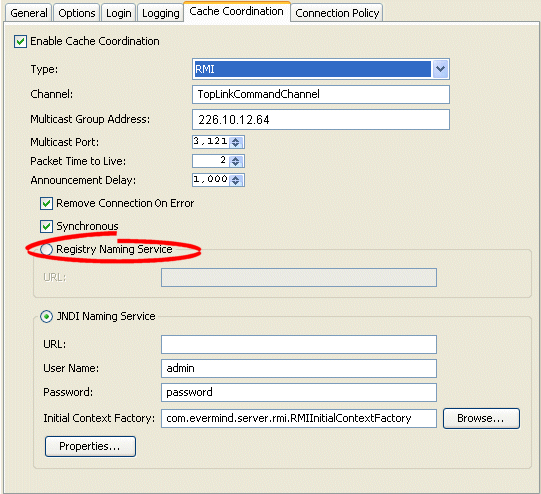
Use the following information to configure the naming service options:
| Field | Description |
|---|---|
| URL | Assuming that you are using the OC4J JNDI naming service and that all the hosts in your coordinated cache can communicate using the OC4J proprietary RMI protocol ORMI on OC4J default port 23791, use a URL similar to the following:
ormi://<session-host-IP>:23791 where |
Use the oracle.toplink.remotecommand.TransportManager method setNamingServiceType as follows:
setNamingServiceType(TransportManager.REGISTRY_NAMING_SERVICE)
Then specify the location of the JNDI naming service by providing its URL. Consider the following:
For an RMI or CORBA coordinated cache, if you are using the OC4J JNDI naming service and all the hosts in your coordinated cache can communicate using the OC4J proprietary RMI protocol ORMI on OC4J default port 23791, use a URL similar to the following:
ormi://<session-host-IP>:23791
where session-host-IP is the IP address of the host on which this session is deployed.
Note that the default protocol value is "ormi", and the default port value is "23791". You can also use the TransportManager.DEFAULT_URL_PROTOCOL and DEFAULT_URL_PORT constants.
For more information, see Section 102.4.4, "Cache Coordination API".
Use the announcement delay option to set the amount of time (in milliseconds) that a session should wait between the time that it is available and the time that it broadcasts its announcement message to the members of the coordinated cache. This additional delay may be necessary to give some systems more time to post their connections into the naming service (see Section 103.6, "Configuring a Naming Service Type").
Table 103-10 summarizes which coordinated caches support announcement delay configuration.
Table 103-10 Coordinated Cache Support for Announcement Delay Configuration
| Coordinated Cache | How to Use Oracle JDeveloper | How to Configure an Announcement Delay Using TopLink Workbench |
How to Use Java |
|---|---|---|---|
|
|
|
|
|
|
|
|
|
|
|
|
|
|
|
|
|
|
|
In addition to announcement delay, you may also need to consider packet time-to-live configuration (see Section 103.12, "Configuring a Packet Time-to-Live").
To specify the announcement delay (in milliseconds) for an RMI coordinated cache, use this procedure:
Select a session or session broker in the Navigator. Its properties appear in the Editor.
Click the Cache Coordination tab. The Cache Coordination tab appears.
Ensure the Enable Cache Coordination option is selected, then select the appropriate coordinated cache Type (see Table 103-10). The cache coordination options appear on the tab.
Figure 103-7 Cache Coordination Tab, Announcement Delay Field
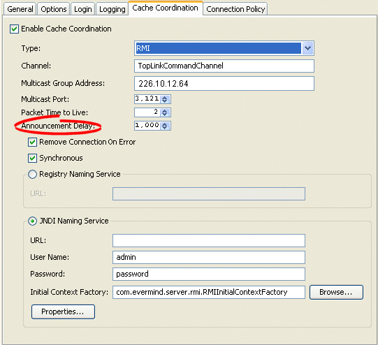
Select the amount of time (in milliseconds) that this session should wait between the time that it is available and the time that it broadcasts its announcement message to the members of the coordinated cache.
Use the oracle.toplink.remotecommand.DiscoveryManager method setAnnouncementDelay to select the amount of time (in milliseconds) that this session should wait between the time that it is available and the time that it broadcasts its announcement message to the members of the coordinated cache
For more information, see Section 102.4.4, "Cache Coordination API".
The session's transport manager creates connections to the various members of the coordinated cache. If a communication error occurs on one of these connections, you can configure the session to either ignore the error or remove the connection.
Table 103-11 summarizes which coordinated caches support connection handling configuration.
Table 103-11 Coordinated Cache Support for Connection Handling Configuration
| Coordinated Cache | How to Use Oracle JDeveloper | How to Configure Connection Handling Using TopLink Workbench |
How to Configure Connection Handling Using Java |
|---|---|---|---|
|
|
|
|
|
|
|
|
|
|
|
|
|
|
|
|
|
|
|
If you configure the session to remove the connection on error, the next time the session tries to communicate with that coordinated cache member, it will construct a new connection.
If you configure the session to ignore the error, the next time the session tries to communicate with that coordinated cache member, it will continue to use the same connection.
To specify how TopLink handles session connections in the event of an error, use this procedure:
Select a session or session broker in the Navigator. Its properties appear in the Editor.
Click the Cache Coordination tab. The Cache Coordination tab appears.
Ensure the Enable Cache Coordination option is selected, then select the appropriate coordinated cache Type (see Table 103-11). The cache coordination options appear on the tab.
Figure 103-8 Cache Coordination Tab, Remove Connection on Error Option
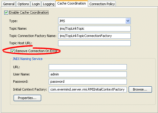
Select the Remove Connection on Error option to configure the session to remove the data source connection in the event of an error.
Use the oracle.toplink.remotecommand.TransportManager method setShouldRemoveConnectionOnError to configure the session to remove the data source connection if an error occurs.
For more information, see Section 102.4.4, "Cache Coordination API".
When you configure a coordinated cache to use a JNDI naming service (see Section 103.6, "Configuring a Naming Service Type"), you can add new environment properties to the environment of the initial JNDI context.
Table 103-12 summarizes which coordinated caches support context properties.
Table 103-12 Coordinated Cache Support for Context Properties
| Coordinated Cache | How to Use Oracle JDeveloper | How to Configure Context Properties Using TopLink Workbench |
How to Configure Context Properties Using Java |
|---|---|---|---|
|
|
|
|
|
|
|
|
|
|
|
|
|
|
|
|
|
|
|
Footnote 1 When JNDI naming service is selected (see Section 103.6, "Configuring a Naming Service Type").
Using TopLink Workbench, TopLink uses the new environment properties you add to create the initial context for both local and remote JNDI access.
Using Java, you can configure different properties for local and remote JNDI access using a session customizer class to call TransportManager methods setLocalContextProperties and setRemoteContectProperties (for more information, see Section 89.8, "Configuring a Session Customizer Class").
To define JNDI context properties, use this procedure:
Select a session or session broker in the Navigator. Its properties appear in the Editor.
Ensure the Enable Cache Coordination option is selected, then select the appropriate coordinated cache Type (see Table 103-12). The cache coordination options appear on the tab.
Ensure the JNDI Naming Service option is selected. See Section 103.6, "Configuring a Naming Service Type".
In the JNDI Naming Service area, click Properties. The Edit Properties dialog box appears.
Use this table to enter data in the following fields on the dialog box.
| Field | Description |
|---|---|
| Name | The name of the property. |
| Value | The value of the property. |
To change (or delete) an existing property, select the property and click Edit (or Remove).
Use the oracle.toplink.remotecommand.TransportManager method setLocalContextProperties to define a Hashtable of the JNDI context properties that will be used to create the initial context for the local JNDI access. Note that the "dedicated.connection" is the default key with the default value of "true".
For more information, see Section 102.4.4, "Cache Coordination API".
The packet time-to-live is the number of hops that session data packets can take before expiring. The default is 2. This allows for a hub and an interface card, and prevents the data packets from leaving the local network. If sessions are hosted on different local area networks (LANs) that are part of wide area network (WAN), or if a firewall configuration prevents it, the announcement sent by one session may not reach the other sessions in the coordinated cache. In this case, consult your network administrator for the correct time-to-live value.
Table 103-13 summarizes which coordinated caches support packet time-to-live configuration.
Table 103-13 Coordinated Cache Support for Packet Time-to-Live Configuration
| Coordinated Cache | How to Use Oracle JDeveloper | How to Configure a Packet Time-to-Live Using TopLink Workbench |
How to Use Java |
|---|---|---|---|
|
|
|
|
|
|
|
|
|
|
|
|
|
|
|
|
|
|
|
In addition to configuring packet time-to-live, you may also need to configure announcement delay (see Section 103.9, "Configuring an Announcement Delay").
To specify the number of hops that session data packets can take before expiring, use this procedure:
Select a session or session broker in the Navigator. Its properties appear in the Editor.
Ensure the Enable Cache Coordination option is selected, then select the appropriate coordinated cache Type (see Table 103-12). The cache coordination options appear on the tab.
Figure 103-10 Cache Coordination Tab, Packet Time to Live Field
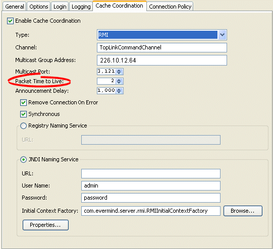
In the Packet Time to Live field, specify the number of hops (default = 2) that session data packets can take before expiring.
Use the oracle.toplink.remotecommand.DiscoveryManager method setPacketTimeToLive to specify the number of hops (default = 2) that session data packets can take before expiring.
For more information, see Section 102.4.4, "Cache Coordination API".