| Oracle® Fusion Middleware Application Adapter Best Practices Guide for Oracle WebLogic Server 11g Release 1 (11.1.1) Part Number E17059-01 |
|
|
View PDF |
| Oracle® Fusion Middleware Application Adapter Best Practices Guide for Oracle WebLogic Server 11g Release 1 (11.1.1) Part Number E17059-01 |
|
|
View PDF |
This chapter lists and describes general best practices that are common to all Oracle Application Adapters for Oracle WebLogic Server.
This chapter discusses the following topics:
Oracle WebLogic Server (WLS) creates and maintains a pool of connections to the iWay J2CA resource adapter. These are called "managed connections". Each managed connection maintains a distinct set of connections to a back-end Enterprise Information System (EIS) systems (exposed as an adapter target). The set is initially empty and becomes populated only as specific adapter target connections are requested by an executing SOA process that is using the managed connection.
A managed connection will maintain only a single connection to any given adapter target and will reuse it each time a connection to that target is requested. When WLS destroys a managed connection, the managed connection will close all its internal EIS connections.
By way of illustration, the following steps detail a scenario in which a SOA process containing references to multiple iWay adapter targets is used.
SOA process requests a managed connection to the iWay resource adapter ("eis/OracleJCAAdapter/DefaultConnection") and receives a new, empty, managed connection called "Managed1".
SOA process invokes a service with adapter target MySAP/SAP1 using Managed1.
Managed1 creates a new MySAP adapter instance, activates it for target SAP1, and adds it to its internal EIS connection set.
Service is invoked, response returned, and SOA process continues.
SOA process invokes a service with adapter target MySAP/SAP2 using Managed1.
Managed1 creates a new MySAP adapter instance, activates it for target SAP2, and adds it to its internal EIS connection set.
Service is invoked, response returned, and SOA process continues.
SOA process invokes a service with adapter target JDEdwards/JDE1 using Managed1.
Managed1 creates a new JDEdwards adapter instance, activates it for target JDE1, and adds it to its internal EIS connection set.
SOA process terminates. WLS returns Managed1 to the connection pool.
After termination of the SOA process, Managed1 is available to be used by some other SOA process. Its internal EIS connections (SAP1, SAP2, JDE1) remain open. They will be reused the next time a process requests connections to those targets from Managed1. They will be closed only when WLS destroys Managed1.
You can monitor the managed connection pool in the WLS admin console, as shown in the following image.
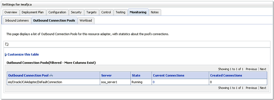
The "current connections" column is the number of managed connections that are currently in use, presumably by executing SOA processes. This number should go up when a SOA process begins execution and should go down after a period of inactivity.
When a SOA process needs a managed connection, it will try to retrieve one from the connection pool. If a managed connection is not available, and the number of current connections does not yet exceed the maximum size of the pool, it will create a new one. If the maximum size of the pool has been reached and no free connection is available, then a resource availability error will be thrown. When a process is finished, the connection is returned to the pool.
It is important to remember that these numbers represent connections to the iWay resource adapter and not to any specific EIS. A single iWay managed connection may contain any number of EIS connections depending upon its usage history. Consequently, there is no way to introspect the number of EIS connections in use by the iWay resource adapter.
The maximum size of the managed connection pool, the minimum size, and other pool parameters can be set in the RAR deployment descriptor ("weblogic-ra.xml") and viewed in the admin console, as shown in the following image.
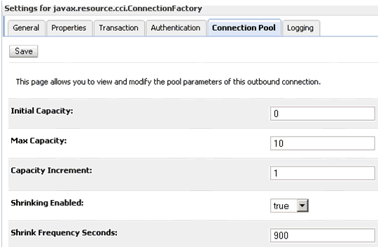
There are many pool parameters, but because they control the pool of connections to the iWay resource adapter and not any specific EIS many of these are immaterial. Setting an initial pool size, for example, accomplishes nothing except creating a set of empty resource adapter connections: iWay managed connections with no internal EIS connections. There is no reason to do this. For similar reasons, the "capacity increment" parameter is also not particularly useful.
You have to set the initial capacity to zero always to work with the iWay adapters.
Note:
You cannot set anything other than the value of zero.Some settings will have implicit effects for all adapter targets. For example, setting a maximum size for the managed connection pool will implicitly establish the maximum number of connections that can be made to any single target since each managed connection can hold at most one connection to a unique adapter target. Similarly, defining the lifetime of a managed connection will implicitly define the lifetime for all EIS connections created by the connection. However, there is no way to control connection pooling for specific EIS targets using the iWay "universal" resource adapter.
Application adapters integrate Oracle WebLogic Server with various packaged applications, such as SAP R/3 and Siebel. These adapters include Oracle Application Adapter for PeopleSoft, Oracle Application Adapter for SAP R/3, Oracle Application Adapter for Siebel, and Oracle Application Adapter for J.D. Edwards OneWorld.
This section describes the steps required to successfully deploy the 11g Release 1 (11.1.1) Oracle Application Adapters in a cluster environment (in all available SOA nodes, which in this case is two machines) and working with inbound and outbound processes.
Before continuing, ensure that the following prerequisites are available:
Two machines with the High Availability (HA) cluster configuration completed successfully. For more information about configuring the HA cluster, see:
http://download.oracle.com/docs/cd/E12839_01/core.1111/e10106/ha_soa.htm#CHDDAHEC
Install Oracle Application Adapters 11g Release 1 (11.1.1) on both machines.
Configure a J2CA configuration as a database repository on the first machine.
Perform the required changes to the ra.xml and weblogic-ra.xml files before deployment.
To deploy the J2CA Connector Application:
Start the Oracle WebLogic Server for the Oracle WebLogic Server domain that has been configured.
Start the SOA_Server1 and SOA_Server2 for both machines.
Open the Oracle WebLogic Server Administration Console in a Web browser by entering the following URL:
http://hostname:port/console
Where hostname is the name of the machine where Oracle WebLogic Server is running and port is the port number for the domain you are using.
The Oracle WebLogic Server Administration Console logon page is displayed.
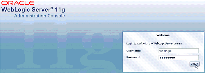
Log in to the Oracle WebLogic Server Administrative Console using an account that has administrator privileges.
The Oracle WebLogic Server Administration Console home page is displayed.
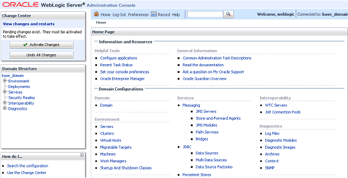
In the Domain Structure section in the left pane, click Deployments.
The Deployments page is displayed.
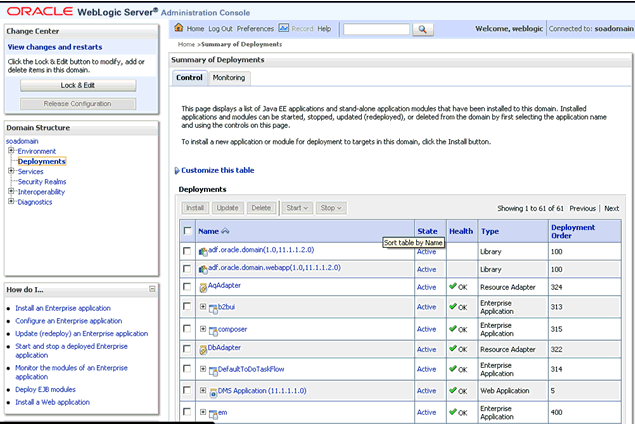
Click Lock & Edit in the Change Center.
Click Install.
The Install Application Assistant page is displayed.
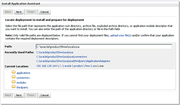
Browse to the following directory:
C:\oracle\product\fmw\soa\soa\thirdparty\ApplicationAdapters\iwafjca.rar
Select the radio button next to iwafjca.rar and click Next.
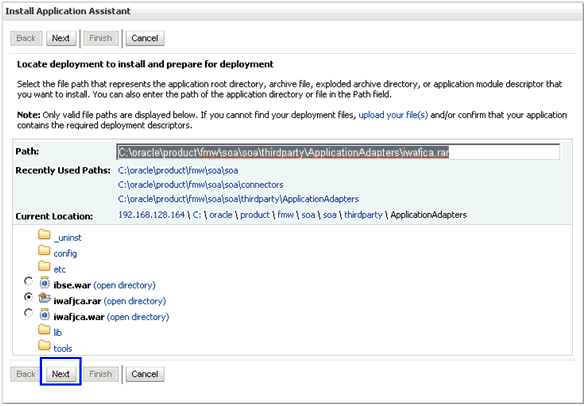
The Choose Targeting Style page is displayed.
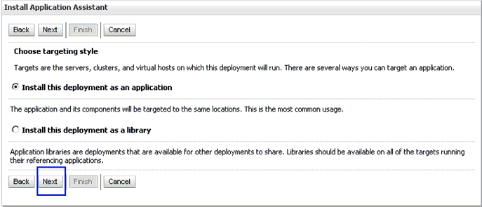
Accept the default selection (Install this deployment as an application) and click Next.
The Select Deployment Target page is displayed.
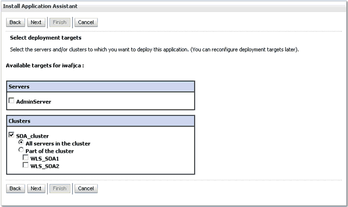
In the Clusters section, select SOA_Cluster followed by All servers in the cluster.
Click Next.
The Optional Settings page is displayed.
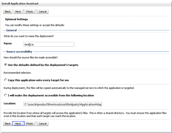
Accept the default values and click Next.
The Summary page is displayed.
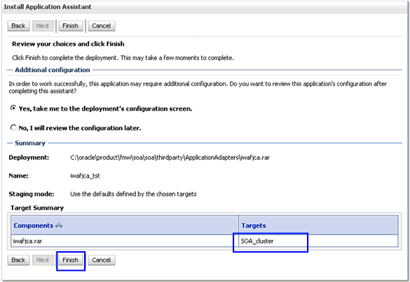
Click Finish.
In the displayed Settings page for the J2CA (iwafjca) Connector Application, click Save.
In the Domain Structure section in the left pane, click Deployments and navigate through the table that lists all the deployed applications and find the J2CA (iwafjca) connector application.
Select the check box next to iwafjca.
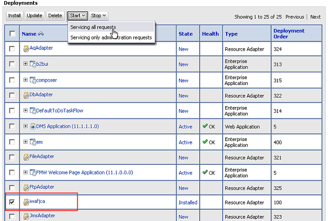
Click the Start submenu (down arrow) and select Servicing all requests.
The Start Application Assistant page is displayed.
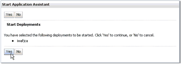
Click Yes.
Verify that the application has successfully started.
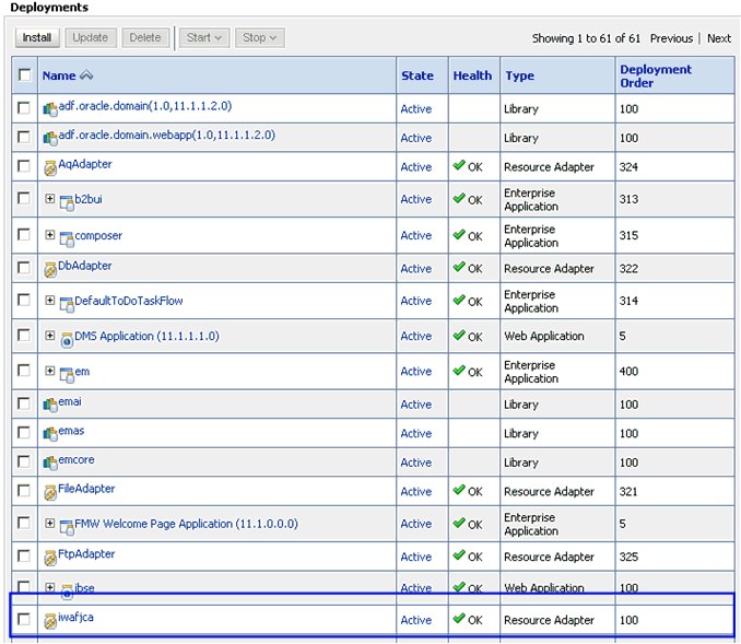
Similarly, repeat steps 5 through 20 for the iwafjca.war deployment.
The following configuration steps must be performed in the Oracle WebLogic Server Administration Console to work with the outbound process:
Open the Oracle WebLogic Server Administration Console in a Web browser by entering the following URL:
http://hostname:port/console
Where hostname is the name of the machine where Oracle WebLogic Server is running and port is the port number for the domain you are using.
The Oracle WebLogic Server Administration Console logon page is displayed.

Log in to the Oracle WebLogic Server Administrative Console using an account that has administrator privileges.
The Oracle WebLogic Server Administration Console home page is displayed.

In the Domain Structure section in the left pane, click Deployments.
The Deployments page is displayed.
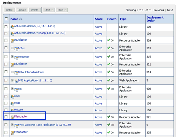
Click FileAdapter.
The Settings for FileAdapter page is displayed.
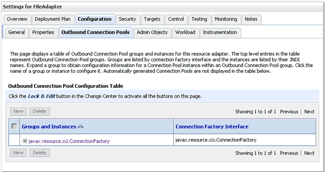
Click the Configuration tab followed by the Outbound Connection Pools tab.
The Outbound Connection Pool Configuration Table page is displayed.
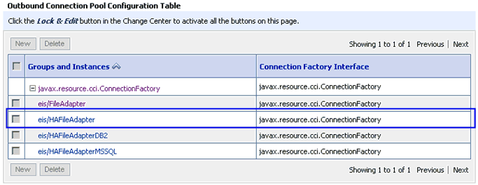
Expand javax.resource.cci.ConnectionFactory and click eis/HAFileAdapter.
The settings for javax.resource.cci.ConnectionFactory page is displayed.
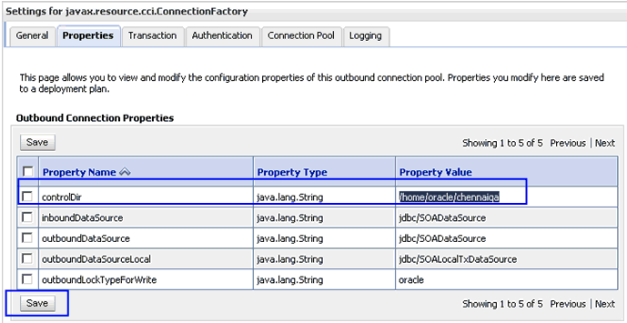
Click the Properties tab.
Provide a valid location for the controlDir property and click Save.
Check if the success message is displayed.
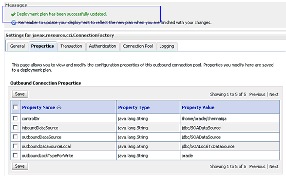
In the Domain Structure section in the left pane, click Deployments.
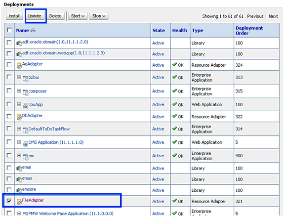
Select FileAdapter from the deployments list and click Update.
The Update Application Assistant page is displayed.
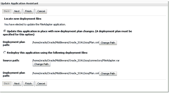
Select Update this application in place with new deployment plan changes and click Next.
The Summary page is displayed.
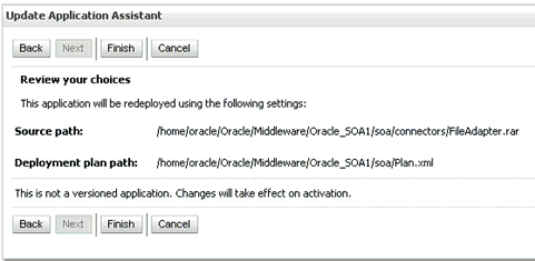
Click Finish.
Check if the success message is displayed.

Copy the generated plan.xml file from the first machine (first node in the cluster configuration) to the same location (Oracle_Home\Middleware\Oracle_SOA1\soa) in the second machine (second node in the cluster configuration).
Restart the servers (Admin_Server, SOA_Server1, SOA_Server2).
Create a shared input location that is accessible by both machines.
For example, if the inputs are pasted in this location, they can be consumed by machine1 and machine2.
To configure the outbound process:
Create a target using Application Explorer on the first machine.
Connect to the target (on the first machine) and create an outbound WSDL for the Oracle Application Adapter for SAP R/3 (MySAP node).
On the second machine, create a target using Application Explorer with the same name as specified on the first machine.
Restart the Admin Server and the soa_servers on both machines.
Create an outbound Mediator process using Oracle JDeveloper with the configuration shown in the following image.
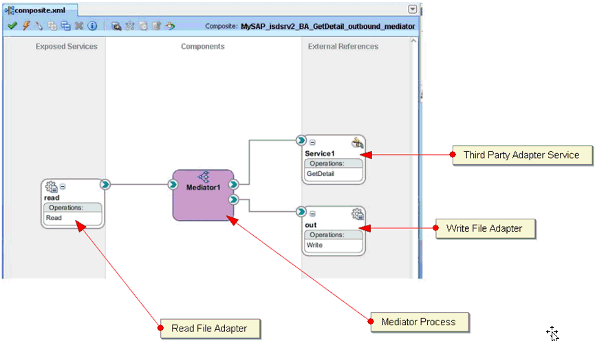
Select the Read_file_adapter.jca file and make the following changes:
Change <connection-factory location="eis/FileAdapter" UIincludeWildcard="*.xml" adapterRef=""/> to <connection-factory location="eis/HAFileAdapter" UIincludeWildcard="*.xml" adapterRef=""/>
Add the value <property name="MaxRaiseSize" value="5"/> to the end.
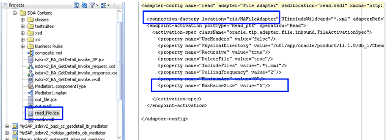
Save the process and deploy the process to both SOA servers.
Provide the input files in the input location configured in the Read file adapter and check if the outputs are shared and placed in the output location (in two machines) configured in the Write file adapter.
The following configuration steps must be completed (for PeopleSoft, Siebel, and J.D. Edwards OneWorld Application Adapters) before executing an inbound process:
Navigate to the following location:
Oracle_Home\product\11.1.0\ohs_1\Oracle_WT1\instances\instance1\config\OHS\ohs1
Open the mod_wl_ohs.conf file.
Add the IP address and port number (port number configured while creating the channel for the adapter) for both machines in the mod_wl_ohs.conf file.
For example (for the PeopleSoft adapter):
<Location /name>SetHandler weblogic-handlerWebLogicCluster machine1_ip:port, machine2_ip:portWLLogFile c:\tmp\psft.log </Location>
Where:
name - Is any appropriate name.
machine1_ip and machine2_ip - Are the machine IP addresses where SOA_Server1 and SOA_Server2 are configured.
port - The port number that is configured in the channel configuration for machine1 and machine2.
Open a command prompt and navigate to:
Oracle_Home\product\11.1.0\ohs_1\Oracle_WT1\instances\instance1\bin
Restart the Oracle HTTP server using the following command:
opmnctl restartproc ias-component=ohs1
When providing the URL in the backend for the adapters (PeopleSoft, Siebel, JDEdwards) the URL must be in the following format:
http://ohsserver_ip:7777/name
Where ohsserver_ip is the IP address of the machine where the Oracle HTTP server is installed and name is the name of the Location configured in the mod_wl_ohs.conf file.
To configure the inbound process:
Create a target and channel using Application Explorer on the first machine.
Connect to the target (on the first machine) and create an inbound WSDL for the Oracle Application Adapter for SAP R/3 (MySAP node).
On the second machine, create a target and channel using Application Explorer with the same name as specified on the first machine.
Restart the Admin Server and the soa_servers on both machines.
Create an inbound Mediator process using Oracle JDeveloper with the configuration shown in the following image.
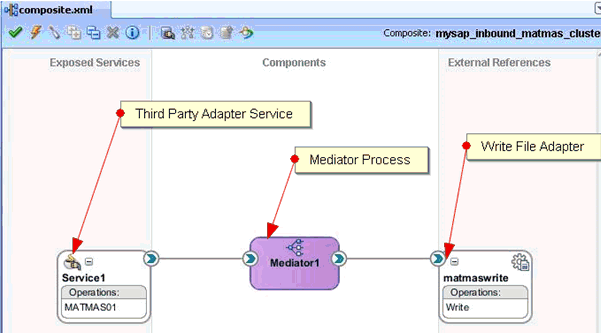
Save the process and deploy the process (to both SOA servers).
Trigger from the backend or use HTTP publisher and check if the output is shared and placed in the output locations (in both machines) that are configured in the Write File adapter.
To perform Singleton testing:
On the first machine, create a target and channel using Application Explorer.
Connect to the target (on the first machine) and create an inbound WSDL for the Oracle Application Adapter for SAP R/3 (MySAP node).
On the second machine, create a target and channel using Application Explorer with the same name as specified on the first machine.
Restart the Admin Server and the soa_servers on both machines.
Create an inbound Mediator process using Oracle JDeveloper with the configuration shown in the following image.
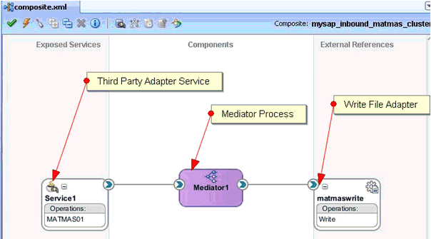
For singleton testing, open the composite.xml file (source view) and add the following property in the Service section:
<property name="singleton">true</property>
For example:
<service name="Service1" ui:wsdlLocation="MATMAS01_receive_cluster.wsdl"><interface.wsdl interface="http://xmlns.oracle.com/pcbpel/iWay/wsdl/MySAP/isdsrv2_cluster/MATMAS01#wsdl.interface(MATMAS01PortType)"/><binding.jca config="MATMAS01_receive_cluster_3P.jca"/><property name="singleton">true</property> </service>
Save the inbound Mediator process and deploy the process to both SOA servers.
Trigger from the backend or use HTTP publisher and check if the messages are received by any one of the machines in the output location.
Stop the soa_server of the machine that is receiving the messages.
Check whether the messages are being received by the second machine.
When you are using the Singleton testing feature with Oracle Application Adapter for SAP R/3, there are some loss of messages (messages are dumped in the SAP GUI). This is caused because the end-point activation of the second system is in progress after the first system is down.
To retrieve the lost messages, perform the following steps:
Login to the SAP GUI.
Enter the /sm58 transaction and navigate to the dumped messages.
Right-click a dumped message, and then select Execute LUW.
Repeat step 3 for all the dumped messages.
All the lost messages are received in the Oracle Enterprise Manager console.
As a best practice, it is recommended to use only a database repository (for example, Oracle) for adapters in development, test, and production environments. Do not use the File repository, which is provided by default only for initial startup purposes. The File repository is not supported for troubleshooting any issues.
This section describes how to generate input XML documents that can be used as payloads for outbound BPEL and Mediator processes.
Before continuing, ensure that the following components and applications are available:
Outbound WSDL document created using Application Explorer.
XML editor (for example, Oracle JDeveloper or Altova XML Spy, which is used as an example in this section).
Oracle WebLogic Server 11g Release 1 (11.1.1) with Oracle JDeveloper Studio.
To create a WSDL document using Application Explorer:
Ensure that Oracle WebLogic Server is started, which is where Application Explorer is deployed.
Start Application Explorer by clicking the Windows Start menu, selecting All Programs, Oracle Application Adapters, and clicking Application Explorer.

You can also start Application Explorer by executing the ae.bat file, which is located in the following directory:
C:\oracle\Middleware\home_0309\Oracle_SOA1\soa\thirdparty\ApplicationAdapters\tools\iwae\bin\ae.bat
Note:
It is a good practice to create a shortcut for the ae.bat file on your desktop.If you are using a UNIX or Linux platform you can start Application Explorer by accessing the iwae.sh file.
Select an available JCA configuration.
Select an appropriate adapter (for example, MySAP).
Create a new target or connect to an existing target.
Expand the created target adapter and select the appropriate object.
Right-click the object and select Create Outbound JCA Service(Request/Response).
The Export WSDL dialog is displayed.
Accept the default location in the Name field and click OK to export the WSDL document to the default location.
You can also click Browse to provide a different location and then click OK, which will export the WSDL document to your defined location.
Navigate to the location where the WSDL document was exported and verify that the WSDL, JCA, Request, and Response schema files are exported and available.
To generate an input XML file from a request schema:
Open an XML editor (for example, Altova XML Spy, which is used as an example in this section).
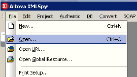
Click File, and then select Open.
The Open dialog is displayed.
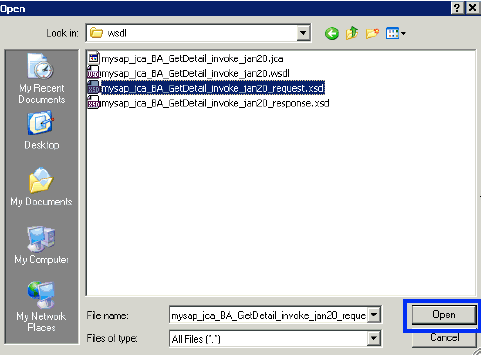
Navigate to the location on your file system where the XML request schema is exported, select the schema file and click Open.
The XML request schema file is opened and displayed in Altova XML Spy.
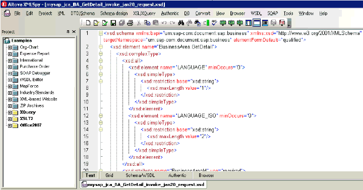
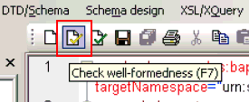
Check if the schema is well formed by clicking Check well-formedness or pressing F7.
Validate the schema by clicking Validate or pressing F8.

Once you have confirmed that the schema is well-formed and valid, click DTD/Schema, and then select Generate Sample XML File.
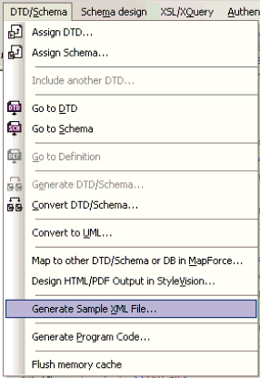
The Generate Sample XML File dialog is displayed.
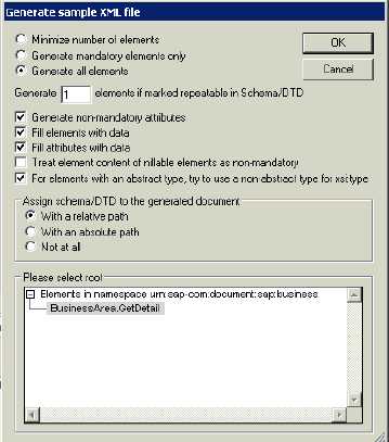
Select the approprate parameters for your sample XML file and click OK when you are ready.
The sample XML file is generated in Altova XML Spy.

Verify that the generated input XML file is well-formed and valid.
The generated input XML file can be used to invoke a BPEL or Mediator process after providing the necessary values in the file.
Before you can use the generated input XML file in the Oracle Enterprise Manager console, verify that the following prerequisites are available:
Mediator Outbound process created in JDeveloper and deployed in SOA_Server1
BPEL Outbound process created in JDeveloper and deployed in SOA_Server1
Mediator Outbound Process
Perform the following steps to use the input XML file in an outbound Mediator process:
Log in to the Oracle Enterprise Manager console by using the following URL:
http://localhost:7001/em
Expand your domain in the left pane followed by the SOA folder.
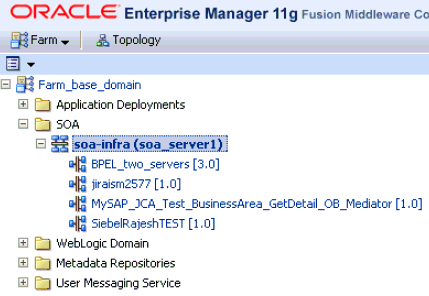
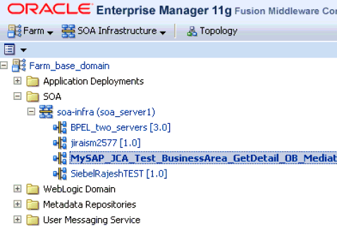
Select an outbound Mediator project (for example, MySAP_JCA_Test_BusinessArea_GetDetail_OB_Mediator).
Click the Test button on the top right-hand corner of the console.
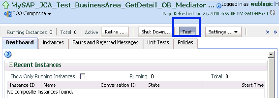
In the Input Arguments section, select XML View from the list and verify that the input XML is displayed.
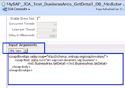
Note:
For Mediator processes, it is mandatory for the input XML to be used with a namespace.The displayed XML in the Oracle Enterprise Manager console can be altered and used as follows:
XML Displayed in the Oracle Enterprise Manager Console
<soap:Envelope xmlns:soap="http://schemas.xmlsoap.org/soap/envelope/"> <soap:Body xmlns:ns1="urn:sap-com:document:sap:business"> <ns1:BusinessArea.GetDetail> </ns1:BusinessArea.GetDetail> </soap:Body> </soap:Envelope>
Altered XML
<soap:Envelope xmlns:soap="http://schemas.xmlsoap.org/soap/envelope/"> <soap:Body xmlns:ns1="urn:sap-com:document:sap:business"> <ns1:BusinessArea.GetDetail BusinessAreaId="1000"> </ns1:BusinessArea.GetDetail> </soap:Body> </soap:Envelope>
The sample input XML that was generated using Altova XML Spy can be used after making the following required modifications:
Remove XML headers.
Add necessary inputs.
Add the soap headers as displayed in the Oracle Enterprise Manager console.
Modify the namespaces to match the namespaces in the input XML.
XML Generated Using Altova XML Spy
<?xml version="1.0" encoding="UTF-8"?> <!--Sample XML file generated by XMLSpy v2008 rel. 2 sp2 (http://www.altova.com)--> <bapi:BusinessArea.GetDetail BusinessAreaId="aaaa" xsi:schemaLocation="urn:sap-com:document:sap:business mysap_jca_BA_GetDetail_invoke_jan20_request.xsd" xmlns:xsi="http://www.w3.org/2001/XMLSchema-instance" xmlns:bapi="urn:sap-com:document:sap:business"> <bapi:LANGUAGE>a</bapi:LANGUAGE> <bapi:LANGUAGE_ISO>aa</bapi:LANGUAGE_ISO> </bapi:BusinessArea.GetDetail>
Altered XML
<soap:Envelope xmlns:soap="http://schemas.xmlsoap.org/soap/envelope/"> <soap:Body xmlns:ns1="urn:sap-com:document:sap:business"> <ns1:BusinessArea.GetDetail BusinessAreaId="1000"> <ns1:LANGUAGE>D</ ns1:LANGUAGE> < ns1:LANGUAGE_ISO>EN</ ns1:LANGUAGE_ISO> </ns1:BusinessArea.GetDetail> </soap:Body> </soap:Envelope>
Click Test Web Service after providing the input XML.
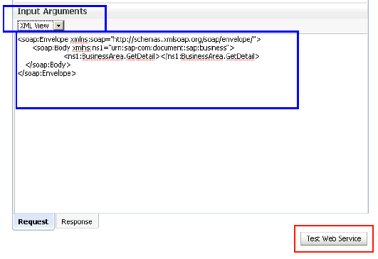
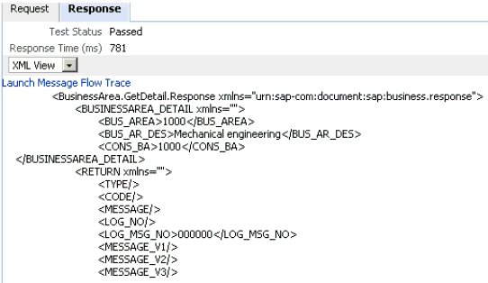
The output is displayed in the Response tab.
BPEL Outbound Process
Perform the following steps to use the input XML file in an outbound BPEL process:
Log in to the Oracle Enterprise Manager console by using the following URL:
http://localhost:7001/em
Expand your domain in the left pane followed by the SOA folder.
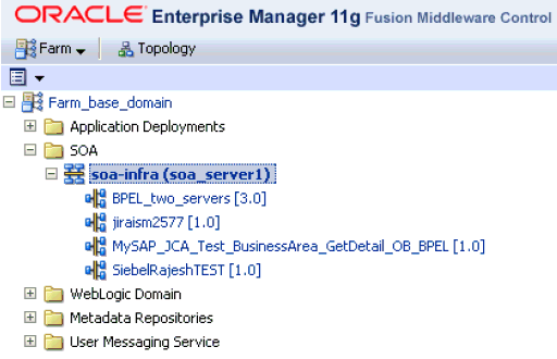
Select an outbound BPEL project (for example, MySAP_JCA_Test_BusinessArea_GetDetail_OB_BPEL).
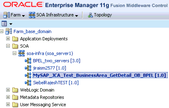
Click the Test button on the top right-hand corner of the console.
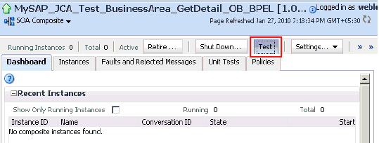
In the Input Arguments section, select XML View from the list and verify that the input XML is displayed.
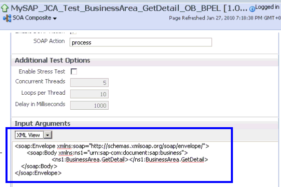
Note:
For BPEL processes, it is not mandatory for the input XML to be used with a namespace.The displayed XML in the Oracle Enterprise Manager console can be altered and used as follows:
XML Displayed in the Oracle Enterprise Manager Console
<soap:Envelope xmlns:soap="http://schemas.xmlsoap.org/soap/envelope/"> <soap:Body xmlns:ns1="urn:sap-com:document:sap:business"> <ns1:BusinessArea.GetDetail> </ns1:BusinessArea.GetDetail> </soap:Body> </soap:Envelope>
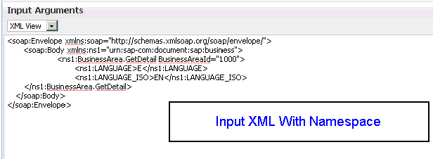
Altered XML With Namespace
<soap:Envelope xmlns:soap="http://schemas.xmlsoap.org/soap/envelope/"> <soap:Body xmlns:ns1="urn:sap-com:document:sap:business"> <ns1:BusinessArea.GetDetail BusinessAreaId="1000"> </ns1:BusinessArea.GetDetail> </soap:Body> </soap:Envelope>
Altered XML Without Namespace
<soap:Envelope xmlns:soap="http://schemas.xmlsoap.org/soap/envelope/"> <soap:Body xmlns="urn:sap-com:document:sap:business"> <BusinessArea.GetDetail BusinessAreaId="1000"> </BusinessArea.GetDetail> </soap:Body> </soap:Envelope>
The sample input XML that was generated using Altova XML Spy can be used after making the following required modifications:
Remove XML headers.
Add necessary inputs.
Add the soap headers as displayed in the Oracle Enterprise Manager console.
Modify or remove the namespaces.
XML Displayed in XML View in the Oracle Enterprise Manager Console
<?xml version="1.0" encoding="UTF-8"?> <!--Sample XML file generated by XMLSpy v2008 rel. 2 sp2 (http://www.altova.com)--> <bapi:BusinessArea.GetDetail BusinessAreaId="aaaa" xsi:schemaLocation="urn:sap-com:document:sap:business mysap_jca_BA_GetDetail_invoke_jan20_request.xsd" xmlns:xsi="http://www.w3.org/2001/XMLSchema-instance" xmlns:bapi="urn:sap-com:document:sap:business"> <bapi:LANGUAGE>a</bapi:LANGUAGE> <bapi:LANGUAGE_ISO>aa</bapi:LANGUAGE_ISO> </bapi:BusinessArea.GetDetail>
Altered XML With Namespace
<soap:Envelope xmlns:soap="http://schemas.xmlsoap.org/soap/envelope/"> <soap:Body xmlns:ns1="urn:sap-com:document:sap:business"> <ns1:BusinessArea.GetDetail BusinessAreaId="1000"> <ns1:LANGUAGE>D</ ns1:LANGUAGE> < ns1:LANGUAGE_ISO>EN</ ns1:LANGUAGE_ISO> </ns1:BusinessArea.GetDetail> </soap:Body> </soap:Envelope>
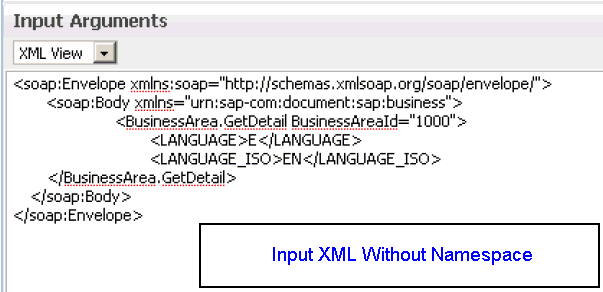
Altered XML Without Namespace
<soap:Envelope xmlns:soap="http://schemas.xmlsoap.org/soap/envelope/"> <soap:Body xmlns="urn:sap-com:document:sap:business"> <BusinessArea.GetDetail BusinessAreaId="1000"> <LANGUAGE>D</ LANGUAGE> < LANGUAGE_ISO>EN</ LANGUAGE_ISO> </BusinessArea.GetDetail> </soap:Body> </soap:Envelope>
Click Test Web Service after providing the input XML with or without a namespace.
The output is displayed in the Response tab.
Input XML With Namespace
Response
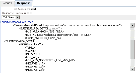
Input XML Without Namespace
Response
