| Oracle® Fusion Middleware Application Adapter for SAP R/3 User's Guide for Oracle WebLogic Server 11g Release 1 (11.1.1.3.0) Part Number E17057-03 |
|
|
View PDF |
| Oracle® Fusion Middleware Application Adapter for SAP R/3 User's Guide for Oracle WebLogic Server 11g Release 1 (11.1.1.3.0) Part Number E17057-03 |
|
|
View PDF |
Oracle Application Adapter for SAP R/3 integrates seamlessly with Business Process Execution Language (BPEL) Process Manager to facilitate Web service integration. Oracle BPEL Process Manager is based on the Service-Oriented Architecture (SOA). It consumes adapter services exposed as Web Service Definition Language (WSDL) documents.
This chapter contains the following topics:
To integrate with Oracle BPEL Process Manager, Oracle Application Adapter for SAP R/3 must be deployed in the same WLS container as Oracle BPEL Process Manager. The underlying adapter services must be exposed as WSDL files, which are generated during design time in Oracle Adapter Application Explorer (Application Explorer) for both request-response (outbound) and event notification (inbound) services of the adapter. For more information, see "Generating WSDL (J2CA Configurations Only)".
The generated WSDL files are used to design the appropriate BPEL processes for inbound or outbound adapter services. A completed BPEL process must be successfully compiled in JDeveloper and deployed to a BPEL server. Upon deployment to the BPEL server, every newly built process is automatically deployed to the Oracle Enterprise Manager console, where you run, monitor, and administer BPEL processes, and listen to adapter events.
During installation, Oracle Application Adapter for SAP R/3 is deployed as a J2CA 1.0 resource adapter within the WLS container. The adapter must be deployed in the same WLS container as Oracle BPEL Process Manager.
To configure a new Application Server connection in Oracle JDeveloper:
Open Oracle JDeveloper on your system.
From the menu bar, click View and select Application Server Navigator, as shown in Figure 5-1.
The Application Server tab is displayed, as shown in Figure 5-2.
Right-click Application Servers and select New Application Server.
The Create Application Server Connection Wizard is displayed, as shown in Figure 5-3.
Figure 5-3 Create Application Server Connection Wizard
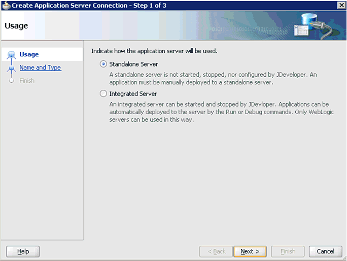
Accept the default selection (Standalone Server) and click Next.
The Name and Type page is displayed, as shown in Figure 5-4.
Specify a new name for the Application Server connection and click Next.
The Authentication page is displayed, as shown in Figure 5-5.
Specify a valid user name (for example, weblogic) and a password (for example, welcome1) for your new connection.
Click Next.
The Configuration page is displayed, as shown in Figure 5-6.
Specify the Oracle WebLogic host name (for example, localhost), which is the system IP where the process must deploy and Oracle WebLogic domain (for example, base_domain).
Click Next.
The Test page is displayed, as shown in Figure 5-7.
Click Test Connection.
Make sure that the test status is successful.
Click Next.
The Finish page is displayed, as shown in Figure 5-8.
Click Finish.
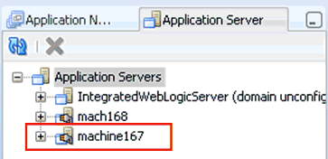
The new Application Server connection is listed in the left pane (Application Server tab), as shown in Figure 5-9.
Figure 5-9 New Application Server Connection
The following tools are required to complete your outbound design-time configuration:
Oracle Adapter Application Explorer (Application Explorer)
Oracle JDeveloper BPEL Designer (JDeveloper) or Eclipse
Note:
The examples in this chapter demonstrate the use of JDeveloper.Before you design a BPEL process, you must generate the respective WSDL file using Application Explorer. For more information, see "Generating WSDL for Request/Response Service".
Perform the following steps to generate a WSDL for request/response service:
Start Application Explorer and connect to a defined MySAP target (a J2CA configuration).
For more information on defining a target and connecting to SAP R/3, see "Defining a Target to SAP R/3".
Expand the MySAP target to which you are connected.
Expand Remote Function Modules, Financial Accounting, 0002 -- Company Code Business Object, and then select BAPI_COMPANYCODE_GETDETAIL, as shown in Figure 5-10.
Right-click the BAPI_COMPANYCODE_GETDETAIL node.
A menu is displayed, as shown in Figure 5-11.
Figure 5-11 BAPI_COMPANYCODE_GETDETAIL Node
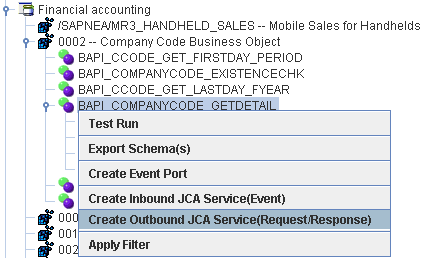
Click Create Outbound JCA Service (Request/Response).
The Export WSDL dialog is displayed, as shown in Figure 5-12.
Click OK.
You can now create an empty composite for SOA, which is the first step that is required to define a BPEL outbound process in JDeveloper.
Perform the following steps to create an empty composite for SOA:
Create a new SOA application.
Enter a name for the new SOA Application and click Next, as shown in Figure 5-13.
The Name your project page is displayed, as shown in Figure 5-14.
Enter a project name (for example, CompanyCode_GD) and click Next.
The Configure SOA settings page is displayed, as shown in Figure 5-15.
From the Composite Template list, select Empty Composite and click Finish.
This section describes how to define a BPEL outbound process, which consists of the following stages:
Configuring a Third Party Adapter Service Component
Configuring an Outbound BPEL Process Component
Configuring a Third Party Adapter Service Component
Perform the following steps to create a third party adapter service component:
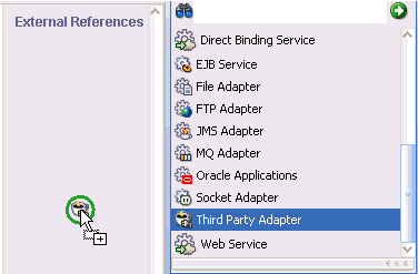
Drag and drop the Third Party Adapter component from the Service Adapters pane to the External References pane, as shown in Figure 5-16.
Figure 5-16 Third Party Adapter Component
The Create Third Party Adapter Service dialog is displayed, as shown in Figure 5-17.
Figure 5-17 Create Third Party Adapter Service Dialog
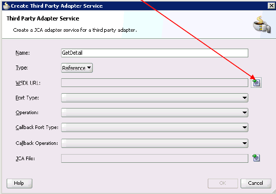
Enter a name for the third party adapter service.
Ensure that Reference is selected from the Type list (default).
Click the Find existing WSDLs icon, which is located to the right of the WSDL URL field.
The SOA Resource Browser dialog is displayed, as shown in Figure 5-18.
Browse and select an outbound WSDL file from the following directory:
<ADAPTER_HOME>\soa\thirdparty\ApplicationAdapters\wsdls
Click OK.
The Localize Files dialog is displayed, as shown in Figure 5-19.
Click OK.
The outbound WSDL file and associated request and response XML schema files (.xsd) are imported to the project folder that has been created.
You are returned to the Create Third Party Adapter Service dialog, as shown in Figure 5-20.
Figure 5-20 Create Third Party Adapter Service Dialog
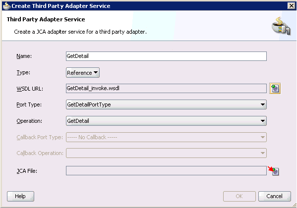
Click the Find JCA file icon, which is located to the right of the JCA File field.
The SOA Resource Browser dialog is displayed, as shown in Figure 5-21.
Browse and select the JCA properties file from the following directory:
<ADAPTER_HOME>\soa\thirdparty\ApplicationAdapters\wsdls
Click OK.
The following message is displayed.
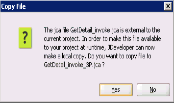
Click Yes.
A copy of the JCA properties file is made in the project folder.
You are returned to the Create Third Party Adapter Service dialog, as shown in Figure 5-22.
Figure 5-22 Create Third Party Adapter Service Dialog
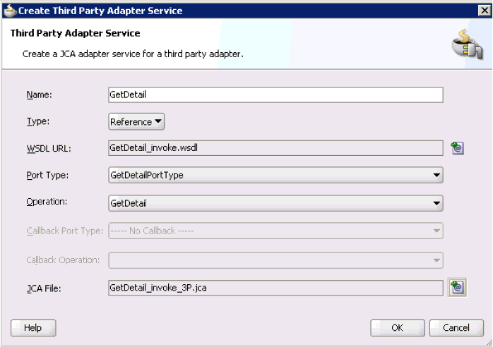
Click OK.
The third party adapter service component (GetDetail) is created and displayed in the External References pane, as shown in Figure 5-23.
Figure 5-23 Third Party Adapter Service Component
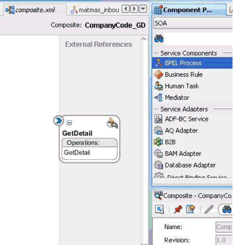
You are now ready to configure an outbound BPEL process component.
Configuring an Outbound BPEL Process Component
Perform the following steps to configure an outbound BPEL process component:
Drag and drop the BPEL Process component from the Service Components pane to the Components pane, as shown in Figure 5-24.
The Create BPEL Process dialog is displayed, as shown in Figure 5-25.
In the Name field, enter a name to identify the new outbound BPEL process component (for example, cc_getdetail).
From the Template list, select Synchronous BPEL Process.
Click the Browse icon, which is located to the right of the Input field to select the associated XML request schema file.
The Type Chooser dialog is displayed, as shown in Figure 5-26.
Expand Project Schema Files, GetDetail_invoke_request.xsd, and select CompanyCode.GetDetail.
Click OK.
You are returned to the Create BPEL Process dialog, as shown in Figure 5-27.
Click the Browse icon, which is located to the right of the Output field to select the associated XML response schema file.
The Type Chooser dialog is displayed, as shown in Figure 5-28.
Expand Project Schema Files, GetDetail_invoke_response.xsd, and select CompanyCode.GetDetailResponse.
Click OK.
You are returned to the Create BPEL Process dialog, as shown in Figure 5-29.
Click OK.
Create a connection between the outbound BPEL process component (cc_ getdetail) and the third party adapter service component (GetDetail), as shown in Figure 5-30.
Double-click the outbound BPEL process component (cc_ getdetail) in the Components pane, as shown in Figure 5-31.
Figure 5-31 Outbound BPEL Process Component
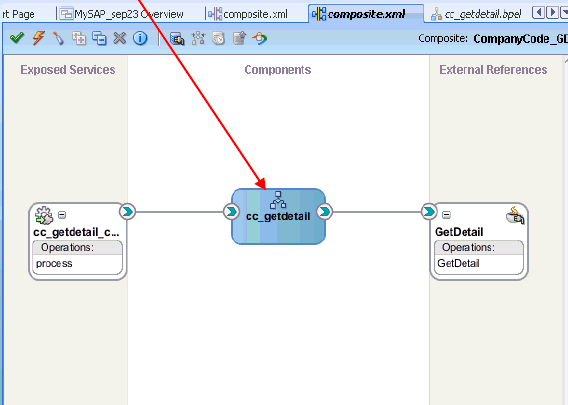
Drag and drop the Invoke activity component to the Components pane and place it between the receiveInput activity component and the replyOutput activity component, as shown in Figure 5-32.
Create a connection between the new Invoke activity component (Invoke_1) and the third party adapter service component (GetDetail), as shown in Figure 5-33.
Double-click the new Invoke activity component (Invoke_1).
The Edit Invoke dialog is displayed, as shown in Figure 5-34.
Click the Plus sign icon, which is located to the right of the Input field to configure a new input variable.
The Create Variable dialog is displayed, as shown in Figure 5-35.
Accept the default values that are provided for the new input variable and click OK.
You are returned to the Edit Invoke dialog, as shown in Figure 5-36.
Click the Plus sign icon, which is located to the right of the Output field to configure a new output variable.
The Create Variable dialog is displayed, as shown in Figure 5-37.
Accept the default values that are provided for the new output variable and click OK.
You are returned to the Edit Invoke dialog, as shown in Figure 5-38.
Click Apply and then OK.
Drag and drop the Assign activity component to the Components pane and place it between the Receive activity component (receiveInput) and the Invoke activity component (Invoke_1), as shown in Figure 5-39.
Double-click the new Assign activity component (Assign_1), as shown in Figure 5-40.
The Assign dialog is displayed, as shown in Figure 5-41.
Click the Copy Operation tab.
Click the Plus sign icon and select Copy Operation from the list of available operations.
The Create Copy Operation dialog is displayed, as shown in Figure 5-42.
In the From pane, expand Variables, InputVariable, and then select payload.
In the To pane, expand Variables, Invoke_1_GetDetail_InputVariable, and then select input_GetDetail.
Click OK.
You are returned to the Assign dialog, as shown in Figure 5-43.
Click Apply and then OK.
Drag and drop the Assign activity component to the Components pane and place it between the Invoke activity (Invoke_1) and the Reply activity (replyOutput), as shown in Figure 5-44.
Double-click the new Assign activity component (Assign_2), as shown in Figure 5-45.
Figure 5-45 New Assign Activity Component
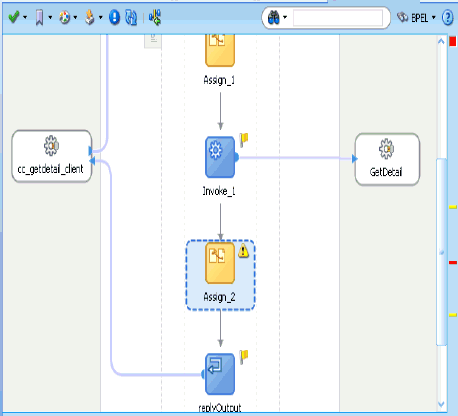
The Assign dialog is displayed, as shown in Figure 5-46.
Click the Copy Operation tab.
Click the Plus sign icon and select Copy Operation from the list of available operations.
The Create Copy Operation dialog is displayed, as shown in Figure 5-47.
In the From pane, expand Variables, Invoke_1_GetDetail_OutputVariable, and then select output_GetDetail.
In the To pane, expand Variables, outputVariable, and then select payload.
Click OK.
You are returned to the Assign dialog, as shown in Figure 5-48.
Click Apply and then OK.
Double-click composite.xml in the left pane, as shown in Figure 5-49.
Click the Save All icon in the menu bar to save the new outbound BPEL process component that was configured, as shown in Figure 5-50.
You are now ready to deploy the BPEL outbound process.
Perform the following steps to deploy the BPEL outbound process.
Right-click the project name in the left pane (for example, CompanyCode_GD), select Deploy, and then click CompanyCode_GD, as shown in Figure 5-51.
The Deployment Action page is displayed, as shown in Figure 5-52.
Ensure that Deploy to Application Server is selected.
Click Next.
The Deploy Configuration page is displayed, as shown in Figure 5-53.
Leave the default values selected and click Next.
The Select Server page is displayed, as shown in Figure 5-54.
Select an available application server that was configured and click Next.
The SOA Servers page is displayed, as shown in Figure 5-55.
Select a target SOA server and click Next.
The Summary page is displayed, as shown in Figure 5-56.
Review and verify all the available deployment information for your project and click Finish.
The process is deployed successfully, as shown in Figure 5-57.
Figure 5-57 Successful Deployment Message

Perform the following steps to invoke the input XML document in the Oracle Enterprise Manager console.
Logon to the Oracle Enterprise Manager console.
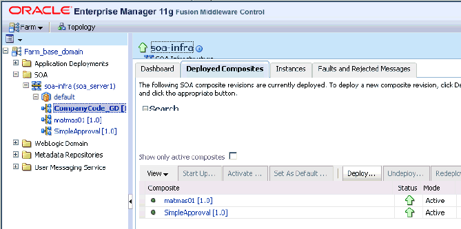
Expand your domain in the left pane followed by the SOA folder.
Select an available project (for example, CompanyCode_GD).
Click Test, as shown in Figure 5-58.
Click the Request tab, as shown in Figure 5-59.
Provide an appropriate input value in the Value field and click Test Web Service.
The output response is received in the Oracle Enterprise Manager console, as shown in Figure 5-60.
Perform the following steps to invoke the input XML document using XML View:
Select XML View from the list, as shown in Figure 5-61.
Provide an appropriate input XML document in the Input Arguments area and click Test Web Service.
The output response is received in the Oracle Enterprise Manager console, as shown in Figure 5-62.
When testing an outbound BPEL process or an outbound Mediator process from the Oracle Enterprise Manager console, do not use the XML envelopes that are generated by these consoles. Instead, remove them and use the XML payloads that are generated from the schemas, which conform to the WSDLs for namespace qualifications.
The Mediator data flows can be tested using the Enterprise Manager console. When creating a Mediator data flow and interactions, the Web services are created and registered with the Oracle Application Server. For more information on creating a Mediator outbound process, see Chapter 6, "Integration With Mediator Service Components in the Oracle SOA Suite".
This section demonstrates how Oracle Application Adapter for SAP R/3 integrates with SAP R/3 to receive event data. In this example, an SAP R/3 event occurs when a customer record is added to a SAP R/3 system.
The following tools are required to complete your adapter design-time configuration:
Oracle Adapter Application Explorer (Application Explorer)
Oracle JDeveloper BPEL Designer (JDeveloper) or Eclipse
Note:
The examples in this chapter demonstrate the use of JDeveloper.Before you design a BPEL process, you must generate the respective WSDL file using Application Explorer. For more information, see "Generating WSDL for Event Integration".
You must create a separate channel for every inbound J2CA service and select that channel when you generate WSDL for inbound interaction using Application Explorer.
Note:
If two or more events share the same channel, then event messages may not be delivered to the right BPEL process.To create a channel:
Start Application Explorer and connect to a J2CA configuration.
In the left pane, expand the Events node.
Expand the MySAP node.
The Ports and Channels nodes appear in the left pane, as shown in Figure 5-63.
Right-click Channels and select Add Channel.
The Add Channel dialog is displayed, as shown in Figure 5-64.
Perform the following steps:
Enter a name for the channel, for example, SAP_Channel.
Enter a brief description (optional).
From the Protocol list, select Application Server - mySAP.
Click Next.
The Application Server dialog is displayed, as shown in Figure 5-65. The following tabs are available:
User (Required)
System (Required)
Security
Advanced
For the User tab, enter the appropriate information for your SAP R/3 channel based on the information in the following table.
| Target Parameter | Description |
|---|---|
|
Client |
The client number defined for the SAP R/3 application for client communications. |
|
User |
A valid user ID for the SAP R/3 application. |
|
Password |
A valid password for the SAP R/3 application. |
|
Authentication Mode |
The authentication mode you want to use when connecting to your SAP R/3 system. By default, Password is selected from the list. |
Click the System tab, as shown in Figure 5-66.
For the System tab, enter the appropriate information for your SAP R/3 channel based on the information in the following table.
Table 5-2 System Tab Parameters
| Target Parameter | Description |
|---|---|
|
Gateway host |
A host name for the SAP R/3 Gateway. |
|
Gateway service |
A service for the SAP R/3 Gateway. |
|
Program ID of the server |
An SAP R/3 program ID you want to use for this channel. |
|
Application Server |
The name of the SAP R/3 application server you are using. |
|
System Number |
An SAP R/3 system number. |
For the Security tab (optional), enter the appropriate information for your SAP R/3 channel based on the information in the following table.
Table 5-3 Security Tab Parameters
| Target Parameter | Description |
|---|---|
|
SNC mode |
By default, SNC is disabled. To enable SNC, select 1 from the list. |
|
SNC partner |
Enter the name of the RFC server or message server (load balancing) that provides the SNC services. |
|
SNC level |
From the list select the version of the SNC library. |
|
SNC name |
Enter the name of the SNC library you are using. |
|
SNC library path |
For the Advanced tab (optional), enter the appropriate information for your SAP R/3 channel based on the information in the following table.
Table 5-4 Advanced Tab Parameters
| Target Parameter | Description |
|---|---|
|
IDOC Format |
Select an IDOC type from the list:
|
|
IDOC release |
The IDOC versioning you want to use for your connection. |
|
IDOC release provider |
The IDOC release provider for your connection. Select IDOC DOCREL field (default), SAP release, or user input from the list. |
|
SAP trace |
Select this option to enable SAP traces. The SAP traces are stored in the following locations during design time and run time: Design Time: <ADAPTER_HOME>\soa\thirdparty\ApplicationAdapters\tools\iwae\bin
Run Time: <ADAPTER_HOME>\user_projects\domains\base_domain
The file name formats that are used for the SAP traces are as follows (for design time and run time):
|
|
Processing Mode |
Select the type of synchronous processing from the list. Possible values include REQUEST and REQUEST_RESPONSE. |
Click OK.
The channel appears under the channels node in the left pane. An X over the icon indicates that the channel is currently disconnected.
Generating WSDL for Event Notification
After you create a channel and verify that it is not started, you must generate WSDL for the event using Application Explorer.
Start Application Explorer.
A list of all adapters is displayed, as shown in Figure 5-67.
Perform the following steps:
Expand the MySAP node.
A list of your available targets is displayed, as shown in Figure 5-68.
Figure 5-68 Disconnected MySAP Target Node
Click a target name under the MySAP node, for example, SAPTarget..
Verify your connection parameters.
Right-click the target name and select Connect.
The x icon disappears, indicating that the node is connected, as shown in Figure 5-69.
Expand the IDOCs node and select DEBMAS.
The DEBMAS list is displayed, as shown in Figure 5-70.
Figure 5-70 DEBMAS Customer Master Data Distribution List

Right-click DEBMAS05 from the DEBMAS list.
Figure 5-71 Create Inbound JCA Service (Event) Option
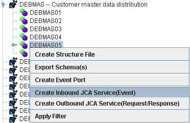
Select Create Inbound JCA Service (Event), as shown in Figure 5-71.
The Export WSDL dialog is displayed, as shown in Figure 5-72.
Perform the following steps:
In the Name field, specify a name for the WSDL file.
From the Channel list, select the channel you created for this inbound service.
Important: You must create a separate channel for every event. Verify that the channel is stopped before run-time.
Three check boxes for Root, Namespace, and Schema validation are also available. Selection of multiple validation options is allowed.
- Root validation is used to validate the root element in the inbound XML document.
- Namespace validation is used to validate the namespace in the inbound XML document.
- Schema validation is used to validate the inbound XML document with the schema in the WSDL document.
During run time, validation is processed based on the validation options that are selected. If multiple validation options are selected, then during run time if the first validation option fails, the remaining validation options are not processed. Root and namespace validations are considered modest levels of validation. Schema validation is a stricter validation level. It is recommended to use root and namespace validation options, unless the root element and namespace are different between the IDOCs in the SAP environment.
You can now create an empty composite for SOA, which is the first step that is required to define a BPEL inbound process in JDeveloper.
Perform the following steps to create an empty composite for SOA:
Create a new SOA application.
Enter a name for the new SOA Application and click Next, as shown in Figure 5-73.
The Name your project page is displayed.
Enter a project name (for example, matmas01) and click Next.
The Configure SOA settings page is displayed, as shown in Figure 5-75.
From the Composite Template list, select Empty Composite and click Finish.
This section describes how to define a BPEL inbound process, which consists of the following stages:
Configuring a Third Party Adapter Service Component
Configuring an Inbound BPEL Process Component
Creating a Third Party Adapter Service Component
Perform the following steps to create a third party adapter service component:
Drag and drop the Third Party Adapter component from the Service Adapters pane to the Exposed Services pane, as shown in Figure 5-76.
Figure 5-76 Third Party Adapter Component
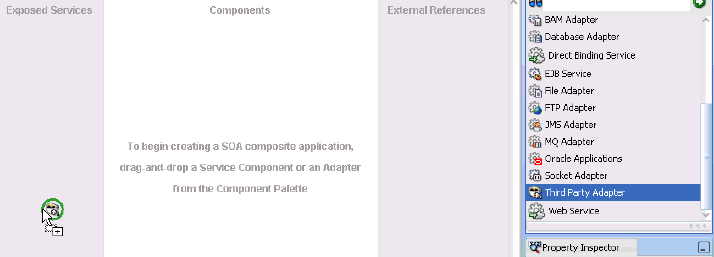
The Create Third Party Adapter Service dialog is displayed, as shown in Figure 5-77.
Figure 5-77 Create Third Party Adapter Service Dialog
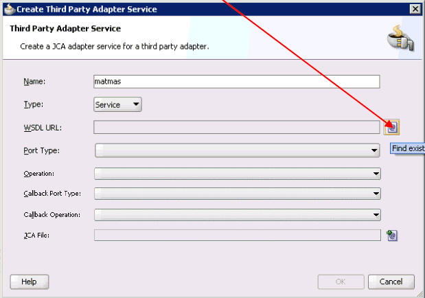
Enter a name for the third party adapter service.
Ensure that Service is selected from the Type list (default).
Click the Find existing WSDLs icon, which is located to the right of the WSDL URL field.
The SOA Resource Browser dialog is displayed, as shown in Figure 5-78.
Browse and select an inbound WSDL file from the following directory:
<ADAPTER_HOME>\soa\thirdparty\ApplicationAdapters\wsdls
Click OK.
The Localize Files dialog is displayed, as shown in Figure 5-79.
Click OK.
The inbound WSDL file and associated receive/request XML schema file (.xsd) are imported to the project folder that has been created.
You are returned to the Create Third Party Adapter Service dialog, as shown in Figure 5-80.
Figure 5-80 Create Third Party Adapter Service Dialog
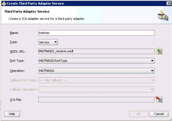
Click the Find JCA file icon, which is located to the right of the JCA File field.
The SOA Resource Browser dialog is displayed, as shown in Figure 5-81.
Browse and select the JCA properties file from the following directory:
<ADAPTER_HOME>\soa\thirdparty\ApplicationAdapters\wsdls
Click OK.
A Copy File message is displayed, as shown in Figure 5-82.
Figure 5-82 Copy File Confirmation Message
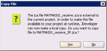
Click Yes.
A copy of the JCA properties file is made in the project folder.
You are returned to the Create Third Party Adapter Service dialog, as shown in Figure 5-83.
Figure 5-83 Create Third Party Adapter Service Dialog
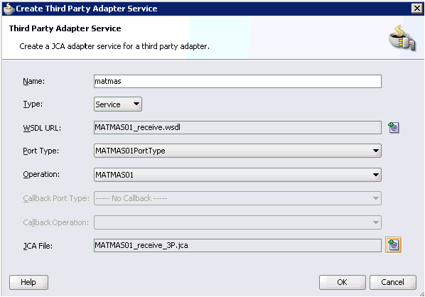
Click OK.
The third party adapter service component (matmas) is created and displayed in the Exposed Services pane, as shown in Figure 5-84.
Figure 5-84 Third Party Adapter Service Component
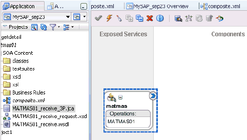
You are now ready to configure an inbound BPEL process component.
Creating an Inbound BPEL Process Component
Perform the following steps to create an inbound BPEL process component:
Drag and drop the BPEL Process component from the Service Components pane to the Components pane, as shown in Figure 5-85.
The Create BPEL Process dialog is displayed, as shown in Figure 5-86.
In the Name field, enter a name to identify the new inbound BPEL process component (for example, matmas_inbound).
From the Template list, select Base on a WSDL.
Uncheck the Expose as SOAP service check box.
Click the Find existing WSDLs icon, which is located to the right of the WSDL URL field.
The SOA Resource Browser dialog is displayed, as shown in Figure 5-87.
Browse and select an inbound WSDL file from the project folder.
For example:
C:\JDeveloper\mywork\MySAP_sep23\matmas01\MATMAS01_receive.wsdl
Click OK.
You are returned to the Create BPEL Process dialog, as shown in Figure 5-88.
Click OK.
Create a connection between the third party adapter service component (matmas) and the inbound BPEL process component (matmas_inbound), as shown in Figure 5-89.
Double-click composite.xml in the left pane.
Click the Save All icon in the menu bar to save the new inbound BPEL process component that was configured, as shown in Figure 5-90.
You are now ready to deploy the BPEL inbound process.
Perform the following steps to deploy the BPEL inbound process.
Right-click the project name in the left pane (for example, matmas01), select Deploy, and click matmas01, as shown in Figure 5-91.
The Deployment Action page is displayed, as shown in Figure 5-92.
Ensure that Deploy to Application Server is selected.
Click Next.
The Deploy Configuration page is displayed, as shown in Figure 5-93.
Leave the default values selected and click Next.
The Select Server page is displayed, as shown in Figure 5-94.
Select an available application server that was configured and click Next.
The SOA Servers page is displayed, as shown in Figure 5-95.
Select a target SOA server and click Next.
The Summary page is displayed, as shown in Figure 5-96.
Review and verify all the available deployment information for your project and click Finish.
The process is deployed successfully, as shown in Figure 5-97.
Figure 5-97 Successful Deployment Message

Once event messages are triggered through SAP GUI, successful instances are received in the Oracle Enterprise Manager console, as shown in Figure 5-98.
Events are generated by activity in an application system. For example, SAP R/3 may generate an event as customer information is updated in the system. For more information on events, see "Configuring an Event Adapter".
The following topics describe how to trigger an event in SAP R/3 and verify event integration using Oracle Application Adapter for SAP R/3.
To trigger an event in SAP R/3:
Start the SAP Workbench and log in to the SAP R/3 system, as shown in Figure 5-99.
Enter the following information in the Send Customers window:
In the Customer field, enter a customer number with a range from 1 to 3, as shown in Figure 5-100.
In the Output type field, enter DEBMAS.
In the Logical system field, specify the logical system you are using with SAP R/3.
Click the check mark icon in the upper left-hand corner, as shown in Figure 5-101.
Ensure DEBMAS appears in the Message type column.
Click the Execute button.
Customer master data is sent to the logical system specified. If a channel in Application Explorer defined the Program ID with the same value, then the channel receives this customer master data from SAP R/3.
To verify your results:
Logon to the Oracle Enterprise Manager console by using the following URL:
http://localhost:7001/em
Expand your domain in the left pane followed by the SOA folder.
Select an available inbound BPEL process (for example, matmas01), as shown in Figure 5-102.
Figure 5-102 Available Inbound BPEL Process
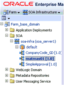
Click the Instances tab.
Recently received run-time event messages are displayed in the Instances tab, as shown in Figure 5-103.
Click the Instance ID to view the received event message.