| Oracle® Fusion Middleware Application Adapter for J.D. Edwards OneWorld User's Guide for Oracle WebLogic Server 11g Release 1 (11.1.1.3.0) Part Number E17058-03 |
|
|
View PDF |
| Oracle® Fusion Middleware Application Adapter for J.D. Edwards OneWorld User's Guide for Oracle WebLogic Server 11g Release 1 (11.1.1.3.0) Part Number E17058-03 |
|
|
View PDF |
Oracle Application Adapter for J.D. Edwards OneWorld integrates seamlessly with Business Process Execution Language (BPEL) Process Manager to facilitate Web service integration. Oracle BPEL Process Manager is based on the Service-Oriented Architecture (SOA). It consumes adapter services exposed as Web Service Definition Language (WSDL) documents.
This chapter contains the following topics:
To integrate with Oracle BPEL Process Manager, Oracle Application Adapter for J.D. Edwards OneWorld must be deployed in the same WLS container as Oracle BPEL Process Manager. The underlying adapter services must be exposed as WSDL files, which are generated during design time in Oracle Application Adapter Application Explorer (Application Explorer) for both request-response (outbound) and event notification (inbound) services of the adapter. For more information, see Chapter 2, "Configuring Oracle Application Adapter for J.D. Edwards OneWorld".
The generated WSDL files are used to design the appropriate BPEL processes for inbound or outbound adapter services. A completed BPEL process must be successfully compiled in Oracle JDeveloper and deployed to a BPEL server. Upon deployment to the BPEL server, every newly built process is automatically deployed to the Oracle Enterprise Manager console, where you run, monitor, administer BPEL processes, and listen to adapter events.
During installation, Oracle Application Adapter for J.D. Edwards OneWorld is deployed as a J2CA 1.0 resource adapter within the WLS container. The adapter must be deployed in the same WLS container as Oracle BPEL Process Manager.
To configure a new Application Server connection in Oracle JDeveloper:
Open Oracle JDeveloper on your system.
From the menu bar, click View and select Application Server Navigator, as shown in Figure 4-1.
The Application Server tab is displayed, as shown in Figure 4-2.
Right-click Application Servers, and then select New Application Server.
The Create Application Server Connection Wizard is displayed, as shown in Figure 4-3.
Figure 4-3 Create Application Server Connection Wizard
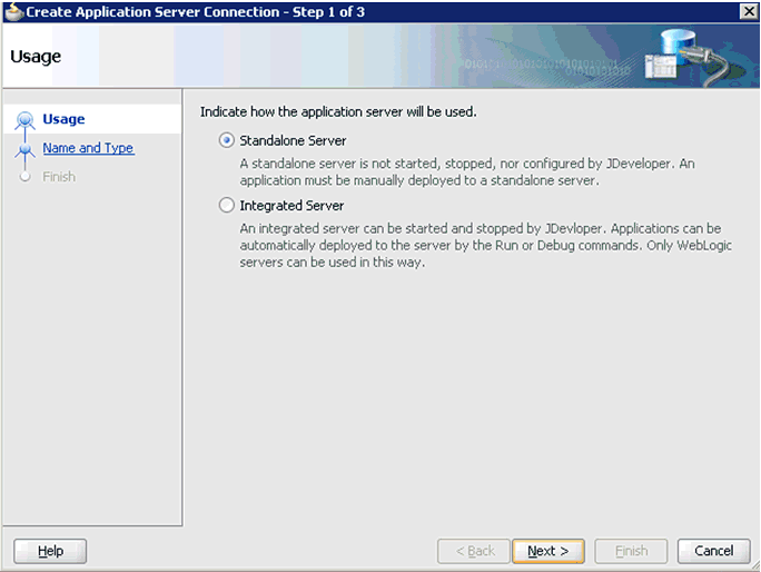
Accept the default selection (Standalone Server) and click Next.
The Name and Type page is displayed, as shown in Figure 4-4.
Specify a new name for the Application Server connection and click Next.
The Authentication page is displayed, as shown in Figure 4-5.
Specify a valid user name (for example, weblogic) and a password (for example, welcome1) for your new connection.
Click Next.
The Configuration page is displayed, as shown in Figure 4-6.
Specify the Oracle WebLogic host name (for example, localhost), which is the machine IP where the process needs to deploy and Oracle WebLogic domain (for example, base_domain).
Click Next.
The Test page is displayed, as shown in Figure 4-7.
Click Test Connection.
Ensure that the test status is successful.
Click Next.
The Finish page is displayed, as shown in Figure 4-8.
Click Finish.
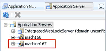
The new Application Server connection is listed in the left pane (Application Server tab), shown in Figure 4-9.
Figure 4-9 New Application Server Connection
The following tools are required to complete your adapter design-time configuration:
Oracle Adapter Application Explorer (Application Explorer)
Oracle JDeveloper BPEL Designer (JDeveloper) or Eclipse
Note:
The examples in this chapter demonstrate the use of Oracle JDeveloper.Before you design a BPEL process, you must generate WSDL using Application Explorer. For more information, see "Generating WSDL for Request/Response Service". The WSDL generated in Application Explorer is used during the BPEL process configuration.
Perform the following steps to generate a WSDL for request/response service:
Start Application Explorer and connect to a defined J.D. Edwards OneWorld target.
For more information, see "Defining a Target to J.D. Edwards OneWorld".
Expand Services, CALLBSFN, and Addressbook.
Figure 4-10 Create Outbound JCA Service(Request/Response) Option
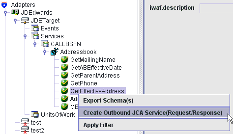
Right-click GetEffectiveAddress, and then select Create Outbound JCA Service (Request/Response), as shown in Figure 4-10.
The Export WSDL dialog is displayed, as shown in Figure 4-11.
Accept the default name for the file.
The .wsdl file extension is added automatically. By default, the names of WSDL files generated for request-response services end with _invoke.
Click OK.
You can now create a new SOA application, which is the first step that is required to define a BPEL outbound process in Oracle JDeveloper.
Perform the following steps to create a new SOA application for the outbound BPEL process:
Open Oracle JDeveloper on your system.
Click Application in the menu bar and select New from the menu, as shown in Figure 4-12.
The Create SOA Application wizard is displayed, as shown in Figure 4-13.
Figure 4-13 Create SOA Application Wizard
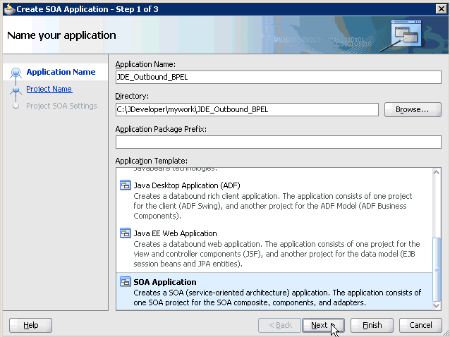
From the Application Template list, click SOA Application.
Enter a name for the new SOA application (for example, JDE_Outbound_BPEL) and click Next.
The Name your project page is displayed, as shown in Figure 4-14.
Enter a project name (for example, GetEffectiveAddress_Invoke) and click Next.
The Configure SOA settings page is displayed, as shown in Figure 4-15.
From the Composite Template list, select Empty Composite and click Finish.
The new SOA application (JDE_Outbound_BPEL) and associated project (GetEffectiveAddress_Invoke) are added to the Application Navigator tab in the left pane, as shown in Figure 4-16.
This section describes how to define a BPEL outbound process, which consists of the following stages:
Configuring a Third Party Adapter Service Component
Configuring an Outbound BPEL Process Component
Configuring a Third Party Adapter Service Component
Perform the following steps to create a third party adapter service component:
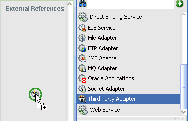
Drag and drop the Third Party Adapter component from the Component Palette tab (Service Adapters section) to the External References pane, as shown in Figure 4-17.
Figure 4-17 Third Party Adapter Component
The Create Third Party Adapter Service dialog is displayed, as shown in Figure 4-18.
Figure 4-18 Create Third Party Adapter Service Dialog
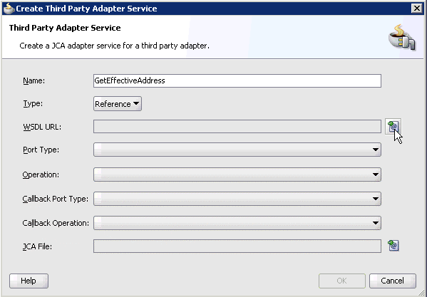
Enter a name for the new third party adapter service.
Ensure that Reference is selected from the Type list (default).
Click the Find existing WSDLs icon, which is located to the right of the WSDL URL field.
The SOA Resource Browser dialog is displayed, as shown in Figure 4-19.
Browse and select an outbound WSDL file (for example, GetEffectiveAddress_invoke.wsdl) from the following directory:
<ADAPTER_HOME>\soa\thirdparty\ApplicationAdapters\wsdls
Click OK.
The Localize Files dialog is displayed, as shown in Figure 4-20.
Click OK.
The outbound WSDL file and associated request and response XML schema files (.xsd) are imported to the project folder that has been created.
You are returned to the Create Third Party Adapter Service dialog, as shown in Figure 4-21.
Figure 4-21 Create Third Party Adapter Service Dialog
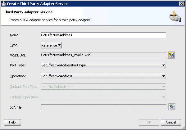
Click the Find JCA Files icon, which is located to the right of the JCA File field.
The SOA Resource Browser dialog is displayed, as shown in Figure 4-22.
Browse and select the JCA properties file (for example, GetEffectiveAddress_invoke.jca) from the following directory:
<ADAPTER_HOME>\soa\thirdparty\ApplicationAdapters\wsdls
Click OK.
The Copy File message is displayed, as shown in Figure 4-23.
Figure 4-23 Copy File Confirmation Message
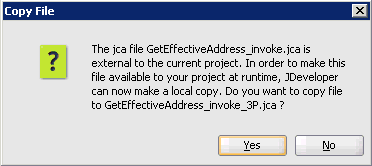
Click Yes.
A copy of the JCA properties file is made in the project folder.
You are returned to the Create Third Party Adapter Service dialog, as shown in Figure 4-24.
Figure 4-24 Create Third Party Adapter Service Dialog
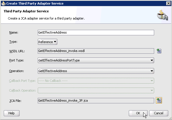
Click OK.
The third party adapter service component (GetEffectiveAddress) is created and displayed in the External References pane, as shown in Figure 4-25.
Figure 4-25 Third Party Adapter Service Component
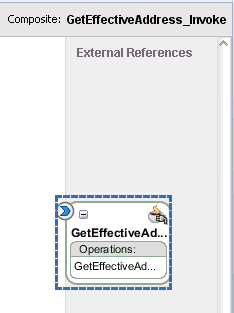
You are now ready to configure an outbound BPEL process component.
Configuring an Outbound BPEL Process Component
Perform the following steps to configure an outbound BPEL process component:
Drag and drop the BPEL Process component from the Component Palette tab (Service Components section) to the Components pane, as shown in Figure 4-26.
The Create BPEL Process dialog is displayed, as shown in Figure 4-27.
In the Name field, enter a name to identify the new outbound BPEL process component (for example, GetEffectiveAddress_Out).
From the Template list, select Synchronous BPEL Process.
Click the Browse Input Elements icon, which is located to the right of the Input field to select the associated XML request schema file.
The Type Chooser dialog is displayed, as shown in Figure 4-28.
Expand Project Schema Files, GetEffectiveAddress_invoke_request.xsd, and select jdeRequest.
Click OK.
You are returned to the Create BPEL Process dialog, as shown in Figure 4-29.
Click the Browse Output Elements icon, which is located to the right of the Output field to select the associated XML response schema file.
The Type Chooser dialog is displayed, as shown in Figure 4-30.
Expand Project Schema Files, GetEffectiveAddress_invoke_response.xsd, and select jdeResponse.
Click OK.
You are returned to the Create BPEL Process dialog, as shown in Figure 4-31.
Click OK.
Create a connection between the outbound BPEL process component (GetEffectiveAddress_Out) and the third party adapter service component (GetEffectiveAddress), as shown in Figure 4-32.
Double-click the outbound BPEL process component (GetEffectiveAddress_Out) in the Components pane, as shown in Figure 4-33.
Figure 4-33 Outbound BPEL Process Component
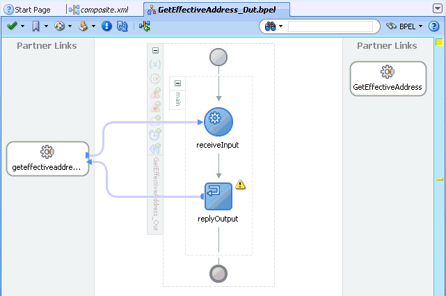
Drag and drop the Invoke activity component to the Components pane and place it between the receiveInput activity component and the replyOutput activity component, as shown in Figure 4-34.
Create a connection between the new Invoke activity component (Invoke_1) and the third party adapter service component (GetEffectiveAddress), as shown in Figure 4-35.
The Edit Invoke dialog is displayed, as shown in Figure 4-36.
Click the Automatically Create Input Variable icon, which is located to the right of the Input field to configure a new input variable.
The Create Variable dialog is displayed, as shown in Figure 4-37.
Accept the default values that are provided for the new input variable and click OK.
You are returned to the Edit Invoke dialog, as shown in Figure 4-38.
Click the Automatically Create Output Variable icon, which is located to the right of the Output field to configure a new output variable.
The Create Variable dialog is displayed, as shown in Figure 4-39.
Accept the default values that are provided for the new output variable and click OK.
You are returned to the Edit Invoke dialog, as shown in Figure 4-40.
Click Apply and then OK.
The Invoke activity component (Invoke_1) is updated accordingly, as shown in Figure 4-41.
Figure 4-41 Invoke Activity Component (Invoke _1)
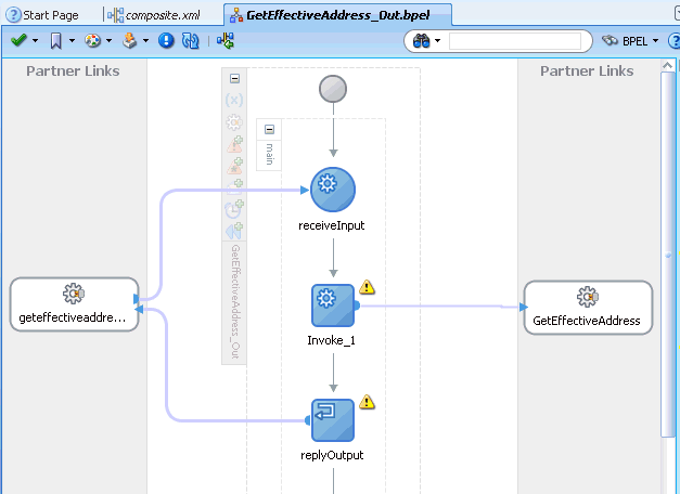
Drag and drop the Assign activity component to the Components pane and place it between the Receive activity component (receiveInput) and the Invoke activity component (Invoke_1), as shown in Figure 4-42.
Double-click the new Assign activity component (Assign_1).
The Assign dialog is displayed, as shown in Figure 4-43.
Click the Copy Operation tab.
Click the Plus sign icon and select Copy Operation from the list of available operations.
The Create Copy Operation dialog is displayed, as shown in Figure 4-44.
In the From pane, expand Variables, InputVariable, and then select payload.
In the To pane, expand Variables, Invoke_1_GetEffectiveAddress_InputVariable, and then select input_GetEffectiveAddress.
Click OK.
You are returned to the Assign dialog, as shown in Figure 4-45.
Click Apply and then OK.
Drag and drop the Assign activity component to the Components pane and place it between the Invoke activity (Invoke_1) and the Reply activity (replyOutput), as shown in Figure 4-46.
Double-click the new Assign activity component (Assign_2).
The Assign dialog is displayed, as shown in Figure 4-47.
Click the Copy Operation tab.
Click the Plus sign icon and select Copy Operation from the list of available operations.
The Create Copy Operation dialog is displayed, as shown in Figure 4-48.
In the From pane, expand Variables, Invoke_1_GetEffectiveAddress_OutputVariable, and then select output_GetEffectiveAddress.
In the To pane, expand Variables, outputVariable, and then select payload.
Click OK.
You are returned to the Assign dialog, as shown in Figure 4-49.
Click Apply and then OK.
The completed activity flow is now displayed, as shown in Figure 4-50.
Double-click composite.xml in the left pane, as shown in Figure 4-51.
Click the Save All icon in the menu bar to save the new outbound BPEL process component that was configured, as shown in Figure 4-52.
You are now ready to deploy the BPEL outbound process.
Perform the following steps to deploy the BPEL outbound process.
Right-click the project name in the left pane (for example, GetEffectiveAddress_Invoke), select Deploy, and then click GetEffectiveAddress_Invoke, as shown in Figure 4-53.
The Deployment Action page is displayed, as shown in Figure 4-54.
Ensure that Deploy to Application Server is selected.
Click Next.
The Deploy Configuration page is displayed, as shown in Figure 4-55.
Leave the default values selected and click Next.
The Select Server page is displayed, as shown in Figure 4-56.
Select an available application server that was configured and click Next.
The SOA Servers page is displayed, as shown in Figure 4-57.
Select a target SOA server and click Next.
The Summary page is displayed, as shown in Figure 4-58.
Review and verify all the available deployment information for your project and click Finish.
The process is deployed successfully, as shown in Figure 4-59.
Figure 4-59 Successful Deployment Message

Perform the following steps to invoke the input XML document in the Oracle Enterprise Manager console.
Log in to the Oracle Enterprise Manager console by using the following URL:
http://localhost:7001/em
Expand your domain in the left pane followed by the SOA folder.
Figure 4-60 Oracle Enterprise Manager Console
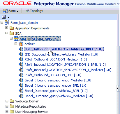
Select an available project (for example, JDE_Outbound_GetEffectiveAddress_BPEL), as shown in Figure 4-60.
Click Test in the right pane, as shown in Figure 4-61.
The Test Web Service page is displayed, as shown in Figure 4-62.
Click the Request tab.
Scroll down to the Input Arguments section, as shown in Figure 4-63.
Select XML View from the list in the upper-left corner.
Provide an appropriate input XML document in the Input Arguments area.
For example:
<soap:Envelope xmlns:soap="http://schemas.xmlsoap.org/soap/envelope/"> <soap:Body xmlns:ns="urn:iwaysoftware:jde/services/CALLBSFN/Addressbook/GetEffectiveAddress"> <ns:jdeRequest sessionidle="" type="callmethod" session=""> <ns:callMethod trans="" app="" returnNullData="yes" name="GetEffectiveAddress" runOnError="yes"> <ns:params> <ns:param name="mnAddressNumber">4242</ns:param> </ns:params> <ns:onError abort="yes"/> </ns:callMethod></ns:jdeRequest> </soap:Body></soap:Envelope>
Click Test Web Service.
The output response is received in the Response tab of the Oracle Enterprise Manager console, as shown in Figure 4-64.
When testing an outbound BPEL process or an outbound Mediator process from the Oracle Enterprise Manager console, do not use the XML envelopes that are generated by these consoles. Instead, remove them and use the XML payloads that are generated from the schemas, which conform to the WSDLs for namespace qualifications.
The Mediator data flows can be tested using the Enterprise Manager console. When creating a Mediator data flow and interactions, the Web services are created and registered with the Oracle Application Server. For more information on creating a Mediator outbound process, see Chapter 5, "Integration With Mediator Service Components in the Oracle SOA Suite".
This section illustrates how Oracle Application Adapter for J.D. Edwards OneWorld integrates with J.D. Edwards OneWorld to receive event data. The design-time and run-time configuration procedures are outlined in the following sections.
The following tools are required to complete your adapter design-time configuration:
Oracle Adapter Application Explorer (Application Explorer)
Oracle JDeveloper BPEL Designer (JDeveloper) or Eclipse
Note:
The examples in this chapter demonstrate the use of Oracle JDeveloper.Before you design a BPEL process, you must generate the respective WSDL file using Application Explorer. For more information, see "Generating WSDL for Event Integration".
Before you design a BPEL process using Oracle JDeveloper, you must create a separate channel for every J2CA event and select that channel when you generate WSDL for inbound interaction using Application Explorer.
Note:
If two or more events share the same channel, then event messages may not be delivered to the right BPEL process.Creating a Channel in Application Explorer
To create a channel:
Right-click the Channels node, and select Add Channels.
The Add Channel dialog is displayed, as shown in Figure 4-65.
In the Name field, enter a descriptive name for the channel.
In the Description field, enter a description (optional).
Click Next.
The dialog is displayed for the selected listener, as shown in Figure 4-66.
Enter the port number of the channel in the Port Number field.
Enter the location of the server in the Host/IP Binding field.
Select the Synchronization type from the Synchronization Type list.
Select Is Length Prefix for events that send data which is not in XML format. The TCP/IP event application must prefix the data with a 4-byte binary length field when writing the data to the TCP/IP port.
Select Is XML for events that send data back in XML format. No preparser is required.
Select Is Keep Alive to maintain a continuous communication between the event transaction and the channel.
Click the PreParser tab, as shown in Figure 4-67.
Enter values based on the table.
| Parameter | Description |
|---|---|
| User id* | A valid user ID for J.D. Edwards OneWorld. |
| User password* | The password associated with the user ID. |
| JDE environment* | Your J.D. Edwards OneWorld environment. For more information about this parameter, see your J.D. Edwards OneWorld documentation or ask your OneWorld system administrator. |
| Application | XMLInterop or the application name in J.D. Edwards OneWorld. Optional. |
| Server IP address* | The name of the server on which J.D. Edwards OneWorld is running. This can be the name of the server, for example, JDEOW, or its IP address, for example, 123.45.67.89. |
| Server Port* | The port number on which the server is listening, for example, 6009. |
| User Role | Define a user role according to your requirements. |
| Schema Location | The location of the XML schema (.xsd file) that was generated from the event output. For example:
<ADAPTER_HOME>\soa\thirdparty\ApplicationAdapters\config\config_name\schemas\JDEdwards\target_name\jde-schema.xsd For more information, see "Generating WSDL for Inbound Interaction". |
| Schema style | Choose from one of the following options:
|
Click OK.
The channel is created and displayed under the Channels node. An X over the icon indicates that the channel is currently disconnected.
Generating WSDL for Event Notification (Command Prompt Only)
You cannot generate WSDL for J.D. Edwards OneWorld event notification using Application Explorer. To generate WSDL from the command prompt, you must perform the following steps.
You can create inbound J2CA service only if the node you have selected supports events.
Note:
The schema validation options (Root, Namespace, Schema) are not applicable for the Oracle Application Adapter for J.D. Edwards OneWorld.To generate a WSDL file for J.D. Edwards OneWorld event notification:
Create a channel in Application Explorer under the J.D. Edwards events node.
Start the channel.
Important: Do not restart the BPEL PM Server or Oracle Application Server after the channel is started.
Send an inbound message from J.D. Edwards OneWorld.
Capture the inbound message payload in the log file located under:
<ADAPTER_HOME>\soa\thirdparty\ApplicationAdapters\config\jca_sample\log\iwaf_jca1500.log
Alternatively, you can create a port with the File protocol under Event in Application Explorer to dispose the event message to the file system.
Use a third party tool such as XMLSpy to create the XSD schema using the XML payload captured in the previous step.
In the generated XML schema (.xsd file) perform the following modifications:
Search for Schemas-jdedwards-com and replace it with iwaysoftware.
Cut the following syntax:
<xs:element name="jdeResponse"><xs:complexType> </xs:complexType> </xs:element>
Paste it before the following line:
<xs:element name="transaction">
Copy the XML schema (.xsd file) from the following directory:
<ADAPTER_HOME>\soa\thirdparty\ApplicationAdapters\config\config_name\schemas\JDEdwards\target_name\
Note:
Edit the created channel by providing the location of the schema (.xsd) file (as mentioned in step 7) in the PreParser tab of Application Explorer. For example:<ADAPTER_HOME>\soa\thirdparty\ApplicationAdapters\config\config_name\schemas\JDEdwards\target_name\jde-schema.xsd
Open a command prompt and navigate to the following directory:
<ADAPTER_HOME>\soa\thirdparty\ApplicationAdapters\tools\iwae\bin
Execute the obadapter.bat file to set the environment.
Navigate to the following directory where the XML schema (.xsd file) is copied:
<ADAPTER_HOME>\soa\thirdparty\ApplicationAdapters\config\config_name\schemas\JDEdwards\target_name\
Enter the following command to generate a WSDL:
java -Diway.oem=oracle11g com.iwaysoftware.af.container.tools.wsdl.IWayWSILBrowser adapterhome adapter target channel schemaPrefix wsdlFileName
where:
adapterhome is the path to your ApplicationAdapters home. For example:
<ADAPTER_HOME>\soa\thirdparty\ApplicationAdapters\
adapter is the name of the adapter. For example, JDEdwards.
target is the name of the adapter target you created in Application Explorer.
channel is the name of the channel you created in Application Explorer.
schemaPrefix is the prefix for the XSD schema. The schema file must be in the same directory where the Java command is executed, for example:
java -Diway.oem=oracle11g com.iwaysoftware.af.container.tools.wsdl.IWayWSILBrowser C:\oracle\Middleware\Oracle_SOA1\soa\thirdparty\ApplicationAdapters\wsdls\JDEdwards jde812_tgt jde_ch Jde812_Schema Jde812_salesorder_receive.wsdl
Once the command is executed, the following is displayed in the command window:
Running Inbound WSDL generation tool...-> user.dir = java com.iwaysoftware.af.container.tools.wsdl.IWayWSILBrowser C:\oracle\Middleware\Oracle_SOA1\soa\thirdparty\wsdls\ApplicationAdapters\JDEdwards jde812_tgt jde_ch Jde812_Schema Jde812_salesorder_receive.wsdl -> Generating WSDL...-> Done.-> Writing WSDL 'C:\oracle\Middleware\Oracle_SOA1\soa\thirdparty\ApplicationAdapters\wsdls\Jde812_salesorder_receive.wsdl ' to disk...-> Done.
Note:
It is good practice to append _receive to the names of WSDL files that are generated for event notification services. This allows you to easily distinguish between them and those generated for request-response services.Stop the channel in Application Explorer.
Note:
You can organize your WSDL files in subfolders, creating your own WSDL hierarchy structure. Create the folders under<ADAPTER_HOME>\soa\thirdparty\ApplicationAdapters\wsdls. The WSIL browser in Oracle JDeveloper displays the full tree structure of your WSDL hierarchy.You can now create a new SOA application, which is the first step that is required to define a BPEL inbound process in Oracle JDeveloper.
Perform the following steps to create a new SOA application for the inbound BPEL process:
Open Oracle JDeveloper on your system.
Click Application in the menu bar and select New from the menu, as shown in Figure 4-68.
The Create SOA Application wizard is displayed, as shown in Figure 4-69.
Figure 4-69 Create SOA Application Wizard
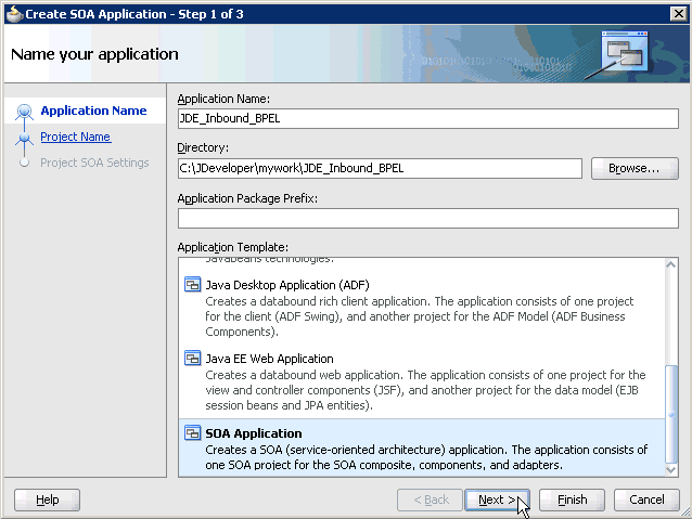
From the Application Template list, click SOA Application.
Enter a name for the new SOA application (for example, JDE_Inbound_BPEL) and click Next.
The Name your project page is displayed, as shown in Figure 4-70.
Enter a project name (for example, Transactions_Receive) and click Next.
The Configure SOA settings page is displayed, as shown in Figure 4-71.
From the Composite Template list, select Empty Composite and click Finish.
The new SOA application (JDE_Inbound_BPEL) and associated project (Transactions_Receive) are added to the Application Navigator tab in the left pane, as shown in Figure 4-72.
This section describes how to define a BPEL inbound process, which consists of the following stages:
Configuring a Third Party Adapter Service Component
Configuring an Inbound BPEL Process Component
Creating a Third Party Adapter Service Component
Perform the following steps to create a third party adapter service component:
Drag and drop the Third Party Adapter component from the Component Palette tab (Service Adapters section) to the Exposed Services pane, as shown in Figure 4-73.
Figure 4-73 Third Party Adapter Component
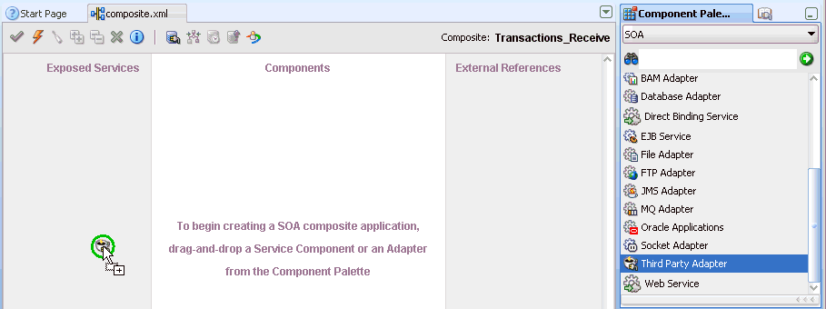
The Create Third Party Adapter Service dialog is displayed, as shown in Figure 4-74.
Figure 4-74 Create Third Party Adapter Service Dialog
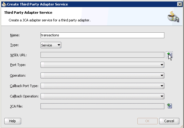
Enter a name for the third party adapter service.
Ensure that Service is selected from the Type list (default).
Click the Find existing WSDLs icon, which is located to the right of the WSDL URL field.
The SOA Resource Browser dialog is displayed, as shown in Figure 4-75.
Browse and select an inbound WSDL file from the following directory:
<ADAPTER_HOME>\soa\thirdparty\ApplicationAdapters\wsdls
Click OK.
The Localize Files dialog is displayed, as shown in Figure 4-76.
Click OK.
The inbound WSDL file and associated receive/request XML schema file (.xsd) are imported to the project folder that has been created.
You are returned to the Create Third Party Adapter Service dialog, as shown in Figure 4-77.
Figure 4-77 Create Third Party Adapter Service Dialog
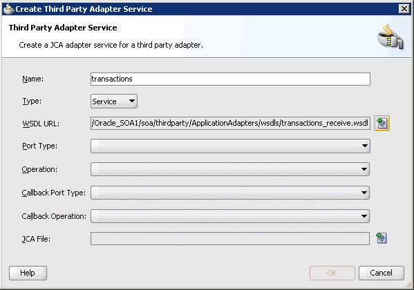
Click the Find JCA Files icon, which is located to the right of the JCA File field.
The SOA Resource Browser dialog is displayed, as shown in Figure 4-78.
Browse and select the JCA properties file from the following directory:
<ADAPTER_HOME>\soa\thirdparty\ApplicationAdapters\wsdls
Click OK.
The Copy File message is displayed, as shown in Figure 4-79.
Figure 4-79 Copy File Confirmation Message
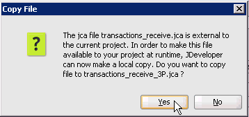
Click Yes.
A copy of the JCA properties file is made in the project folder.
You are returned to the Create Third Party Adapter Service dialog, as shown in Figure 4-80.
Figure 4-80 Create Third Party Adapter Service Dialog
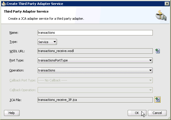
Click OK.
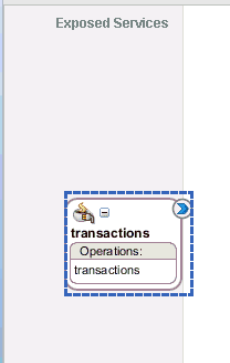
The third party adapter service component (transactions) is created and displayed in the Exposed Services pane, as shown in Figure 4-81.
Figure 4-81 Third Party Adapter Service Component
You are now ready to configure an inbound BPEL process component.
Creating an Inbound BPEL Process Component
Perform the following steps to create an inbound BPEL process component:
Drag and drop the BPEL Process component from the Component Palette tab (Service Components section) to the Components pane, as shown in Figure 4-82.
The Create BPEL Process dialog is displayed, as shown in Figure 4-83.
In the Name field, enter a name to identify the new inbound BPEL process component (for example, Transactions_Inbound).
From the Template list, select Base on a WSDL.
Uncheck the Expose as a SOAP Service check box.
Click the Find existing WSDLs icon, which is located to the right of the WSDL URL field.
The SOA Resource Browser dialog is displayed, as shown in Figure 4-84.
Browse and select an inbound WSDL file (for example, transactions_receive.wsdl) from the project folder.
Click OK.
The Localize Files dialog is displayed, as shown in Figure 4-85.
Click OK.
You are returned to the Create BPEL Process dialog, as shown in Figure 4-86.
Click OK.
Create a connection between the third party adapter service component (transactions) and the inbound BPEL process component (Transactions_Inbound), as shown in Figure 4-87.
Double-click composite.xml in the left pane, as shown in Figure 4-88.
Click the Save All icon in the menu bar to save the new inbound BPEL process component that was configured, as shown in Figure 4-89.
You are now ready to deploy the BPEL inbound process.
Perform the following steps to deploy the BPEL inbound process.
Right-click the project name in the left pane (for example, Transactions_Receive), select Deploy, and then click Transactions_Receive, as shown in Figure 4-90.
The Deployment Action page is displayed, as shown in Figure 4-91.
Ensure that Deploy to Application Server is selected.
Click Next.
The Deploy Configuration page is displayed, as shown in Figure 4-92.
Leave the default values selected and click Next.
The Select Server page is displayed, as shown in Figure 4-93.
Select an available application server that was configured and click Next.
The SOA Servers page is displayed, as shown in Figure 4-94.
Select a target SOA server and click Next.
The Summary page is displayed, as shown in Figure 4-95.
Review and verify all the available deployment information for your project and click Finish.
Once event messages are triggered through J.D. Edwards OneWorld, successful instances are received in the Oracle Enterprise Manager console.
Events are generated by activity in a database or in an application system. You can use events to trigger an action in your application. To trigger an event in J.D. Edwards OneWorld:
Log in to your J.D. Edwards OneWorld system.
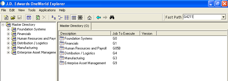
In the Fast Path field of the J.D. Edwards OneWorld Explorer window, type G4211 and press Enter, as shown in Figure 4-96.
Figure 4-96 J.D. Edwards OneWorld Explorer Window
Right-click Sales Order Detail (P4210).
Select Prompt for, and then Values, as shown in Figure 4-97.
The Processing Options dialog is displayed, as shown in Figure 4-98.
Perform the following steps:
Click the Interop tab.
In the Transaction Type field, type JDESOOUT.
Verify that the value in the Before/After Image Processing Blank field is 1.
Click OK.
The Sales Order Detail - (Customer Service Inquiry) window is displayed, as shown in Figure 4-99.
Click the Add icon (third icon from left).
Enter the values as shown in Figure 4-100.
To move to a different field, use the Tab key on your keyboard.
Enter a value for Quantity Ordered and Item Number, as shown in Figure 4-101.
Click the first field in the second row and allow a few seconds for processing, as shown in Figure 4-102.
Click OK.
An event is triggered in the J.D. Edwards OneWorld system.
To verify your results:
Log in to the Oracle Enterprise Manager console by using the following URL:
http://localhost:7001/em
Expand your domain in the left pane followed by the SOA folder.
Figure 4-103 Oracle Enterprise Manager Console
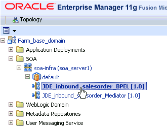
Select an available project (for example, JDE_Inbound_salesorder_BPEL), as shown in Figure 4-103.
Click the Instances tab in the right pane, as shown in Figure 4-104.
Recently received run-time events are displayed in the Instances tab, as shown in Figure 4-105.
Select a J.D. Edwards OneWorld instance ID.
The Flow Trace page is displayed, as shown in Figure 4-106.
Select a component instance to view its detailed audit trail.
The Instance page for the selected component is displayed, as shown in Figure 4-107.
Click the Audit Trail tab to view the event message.
The message received from the J.D. Edwards OneWorld system is displayed in the Audit Trail tab.