| Oracle® Fusion Middleware Application Adapter for J.D. Edwards OneWorld User's Guide for Oracle WebLogic Server 11g Release 1 (11.1.1.3.0) Part Number E17058-03 |
|
|
View PDF |
| Oracle® Fusion Middleware Application Adapter for J.D. Edwards OneWorld User's Guide for Oracle WebLogic Server 11g Release 1 (11.1.1.3.0) Part Number E17058-03 |
|
|
View PDF |
Oracle Application Adapter for J.D. Edwards OneWorld integrates seamlessly with Oracle Service Bus (OSB) to facilitate Web service integration. OSB is based on the Service-Oriented Architecture (SOA). It consumes adapter services exposed as Web Service Definition Language (WSDL) documents.
This chapter contains the following topics:
Overview of Application Adapter Integration with Oracle Service Bus
Configuring Outbound Processing Using Oracle Service Bus (J2CA Configuration)
Configuring Inbound Processing Using Oracle Service Bus (J2CA Configuration)
Configuring Outbound Processing Using Oracle Service Bus (BSE Configuration)
To integrate with Oracle Service Bus (OSB), Oracle Application Adapter for J.D. Edwards OneWorld must be deployed in the same Oracle WebLogic Server as OSB. The underlying adapter services must be exposed as WSDL files, which are generated during design time in Oracle Adapter Application Explorer (Application Explorer) for both request-response (outbound) and event notification (inbound) services of the adapter.
This section describes how to configure outbound processing using Oracle Service Bus for J2CA configurations.
This section includes the following topics:
Setting the Class Path for Application Explorer to Integrate With Oracle Service Bus
Publishing a WSDL From Application Explorer to Oracle Service Bus
Perform the following steps to start Oracle Service Bus and create project folders:
Start the Oracle WebLogic Server for the Oracle WebLogic Server domain that you have configured.
Open the Oracle Service Bus Console in a Web browser by entering the following URL:
http://hostname:port/sbconsole
Where hostname is the name of the machine where Oracle WebLogic Server is running and port is the port for the domain you are using. The port for the default domain is 7001.
The Oracle Service Bus Console logon page is displayed.
Log on to the Oracle Service Bus Console using a valid user name and password.
The Oracle Service Bus Console home page is displayed, as shown in Figure 7-1.
Click Create in the Change Center area to start a new Oracle Service Bus session, as shown in Figure 7-2.
Click Project Explorer in the left pane, as shown in Figure 7-3.
The Project Explorer page is displayed, as shown in Figure 7-4.
Provide a valid name for the new project (for example, JDE_Project) and click Add Project.
The project is successfully created and listed.
Click on the created project.
The project page is displayed, as shown in Figure 7-5.
In the Enter New Folder Name field, type Business Service and click Add Folder.
In the Enter New Folder Name field, type Proxy Service and click Add Folder.
In the Enter New Folder Name field, type wsdls and click Add Folder.
The Business Service, Proxy Service, and wsdls folders are listed in the left pane below the project node. as shown in Figure 7-6.
Before starting and using Application Explorer to publish a WSDL directly to the Oracle Service Bus (OSB) Console (project/folder), OSB users must perform the following steps:
Open the command prompt window.
Navigate to the following directory:
<OSB_Home>\user_projects\domains\base_domain\bin
Execute setDomainEnv.cmd (Windows) or . ./setDomainEnv.sh (UNIX/Linux).
This command sets the class path for Application Explorer to access the Oracle WebLogic Server APIs to publish the WSDLs to the OSB Console.
Do not close the command prompt window.
Navigate to the following directory:
<OSB_Home>\3rdparty\ApplicationAdapters\tools\iwae\bin
Execute ae.bat (Windows) or iwae.sh (UNIX/Linux) to start Application Explorer.
You are now ready to publish WSDLs from Application Explorer to the OSB Console.
Perform the following steps to publish a WSDL from Application Explorer to Oracle Service Bus:
Start Application Explorer, connect to a J2CA configuration, and connect to a J.D. Edwards OneWorld target.
For more information, see Chapter 2, "Configuring Oracle Application Adapter for J.D. Edwards OneWorld".
Expand Services, CALLBSFN, and Addressbook, as shown in Figure 7-7.
Figure 7-7 Create Outbound JCA Service (Request/Response) Option
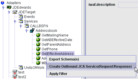
Right-click GetEffectiveAddress, and then select Create Outbound JCA Service (Request/Response).
The Export WSDL dialog is displayed, as shown in Figure 7-8.
In the Name field, a default file name for the WSDL file is provided. You can accept the default or provide your own.
Select the Export to OSB option.
In the Location field, enter the folder name in Oracle Service Bus where you want to publish the WSDL document.
The location is composed of an Oracle Service Bus project name and optionally, one or more folder names. The project name and any folder names must be separated by a forward slash character “/”.
In the Host field, enter the name of the machine where Oracle Service Bus is installed.
In the Port field, enter the port that is being used by Oracle Service Bus.
In the User field, enter your username to access Oracle Service Bus.
In the Password field, enter your password to access Oracle Service Bus.
Click OK.
The WSDL is published to the location specified in the Export WSDL dialog and is now available for use with a Business Service or Proxy Service in Oracle Service Bus.
Open the Oracle Service Bus Console and select the created WSDL folder in the left pane (for example, wsdls), as shown in Figure 7-9.
Ensure that the exported WSDL is listed, as shown in Figure 7-10.
Click the icon that corresponds to the exported WSDL in the Actions column.
The Generate WSDL and Service page is displayed, as shown in Figure 7-11.
Figure 7-11 Generate WSDL and Service Page
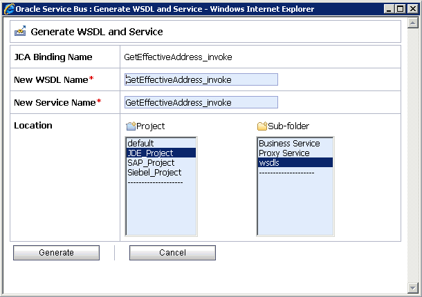
Provide a new WSDL name and a new service name in the corresponding fields, as shown in Figure 7-12.
Figure 7-12 Generate WSDL and Service Page
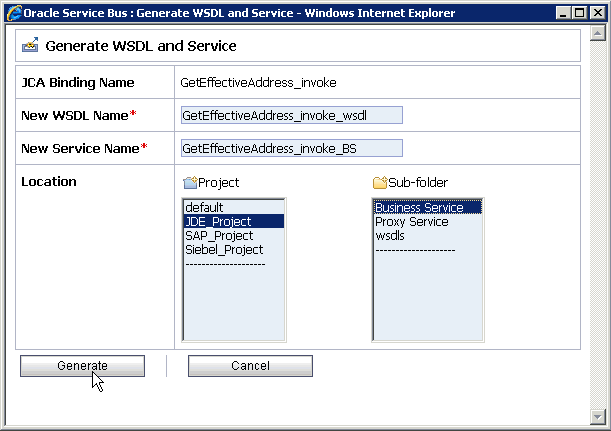
In the Location area, select an available project and the sub-folder that is designated for Business Services.
Click Generate.
If the WSDL and Service resources are successfully created, then the following message is displayed, as shown in Figure 7-13.
Perform the following steps to configure a File type Business Service:
Select the Business Service folder you created in the left pane, as shown in Figure 7-14.
In the right pane, select Business Service from the Create Resource menu, as shown in Figure 7-15.
The General Configuration page is displayed, as shown in Figure 7-16.
Provide a name for the Business Service and from the Service Type area select Messaging Service.
Click Next.
The Message Type Configuration page is displayed, as shown in Figure 7-17.
Figure 7-17 Message Type Configuration Page
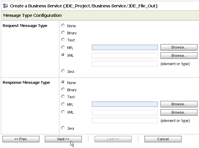
Select XML as the Request Message Type and None as the Response Message Type.
Click Next.
The Transport Configuration page is displayed, as shown in Figure 7-18.
Select file from the Protocol list.
Enter the path to a destination folder on your file system in the Endpoint URI field and click Add.
Click Next, as shown in Figure 7-19.
The FILE Transport Configuration page is displayed, as shown in Figure 7-20.
Figure 7-20 FILE Transport Configuration Page
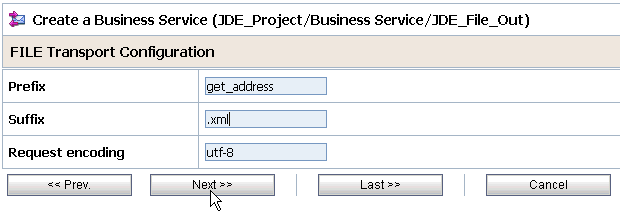
Enter the prefix and suffix for the output file to be received and click Next.
The Message Handling and Advanced Settings page is displayed, as shown in Figure 7-21.
Figure 7-21 Message Handling and Advanced Settings Page

Click Next.
The following Summary page is displayed, as shown in Figure 7-22.
Review all the information for your Business Service and click Save.
Check if the success message is displayed and click Activate in the Change Center, as shown in Figure 7-23.
Figure 7-23 Change Center Activate Button

The Activate Session page is displayed, as shown in Figure 7-24.
Click Submit.
Check if the View Configuration Changes page is displayed, as shown in Figure 7-25.
Figure 7-25 View Configuration Changes Page

Perform the following steps to configure a Proxy Service:
Select the Proxy Service folder you created in the left pane, as shown in Figure 7-26.
Figure 7-26 Create Resource Menu Proxy Service
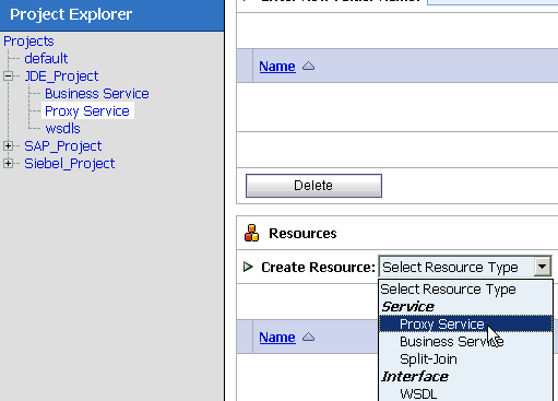
In the right pane, select Proxy Service from the Create Resource menu.
The General Configuration page is displayed, as shown in Figure 7-27.
Provide a name for the Proxy Service and from the Service Type area select Any XML Service.
Click Next, as shown in Figure 7-28.
Select file from the Protocol list.
Enter the path to an input folder on your file system in the Endpoint URI field.
Click Next, as shown in Figure 7-29.
Figure 7-29 FILE Transport Configuration Page
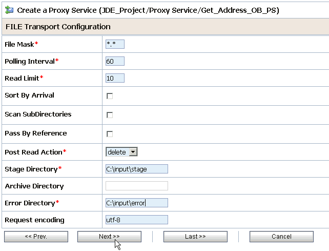
Provide any folder locations on your file system for the Stage Directory and Error Directory fields.
Click Next, as shown in Figure 7-30.
Accept the default values and click Next.
The following Summary page is displayed, as shown in Figure 7-31.
Review all the information for your Proxy Service and click Save.
Check if the success message is displayed, as shown in Figure 7-32.
Perform the following steps to configure a Pipeline:
Click the Edit Message Flow icon in the row of the Proxy Service you created, as shown in Figure 7-33.
The Edit Message Flow workspace area is displayed, as shown in Figure 7-34.
Figure 7-34 Edit Message Flow Workspace Area

Click the Proxy Service icon and select Add Pipeline Pair from the menu.
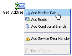
Click the PipelinePairNode1 icon and select Add Route from the menu, as shown in Figure 7-35.
The RouteNode1 icon is added below the Request Pipeline icon, as shown in Figure 7-36.
Click the RouteNode1 icon and select Edit Route from the menu.
The Edit Stage Configuration workspace area is displayed, as shown in Figure 7-37.
Figure 7-37 Edit Stage Configuration Workspace Area
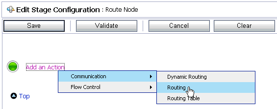
Click Add an Action, select Communication from the menu, and click Routing, as shown in Figure 7-38.
Figure 7-38 Edit Stage Configuration Workspace Area
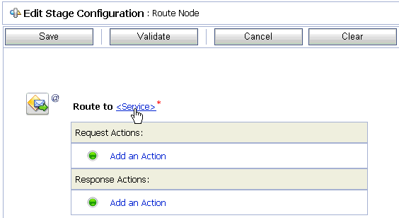
Click <Service>.
The Select Service dialog is displayed, as shown in Figure 7-39.
Select a WSDL type Business Service and click Submit.
You are returned to the Edit Stage Configuration workspace area, as shown in Figure 7-40.
Figure 7-40 Edit Stage Configuration Workspace Area
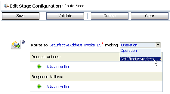
Select the name of the J.D. Edwards OneWorld business object (for example, GetEffectiveAddress) as the operational attribute from the list, as shown in Figure 7-41.
Click Save, as shown in Figure 7-42.
Click the Response Pipeline icon and select Add Stage from the menu.
The Stage1 icon is added below the Response Pipeline icon, as shown in Figure 7-43.
Click the Stage1 icon and select Edit Stage from the menu.
The Edit Stage Configuration workspace area is displayed, as shown in Figure 7-44.
Figure 7-44 Edit Stage Configuration Workspace Area
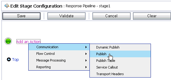
Click Add an Action, select Communication from the menu, and click Publish, as shown in Figure 7-45.
Figure 7-45 Edit Stage Configuration Workspace Area
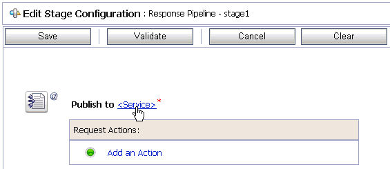
Click <Service>.
The Select Service dialog is displayed, as shown in Figure 7-46.
Select a File type Business Service and click Submit.
You are returned to the Edit Stage Configuration workspace area, as shown in Figure 7-47.
Figure 7-47 Edit Stage Configuration Workspace Area
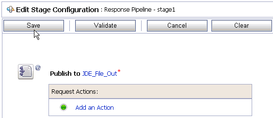
Click Save.
You are returned to the Edit Message Flow workspace area, as shown in Figure 7-48.
Figure 7-48 Edit Message Flow Workspace Area
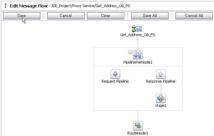
Click Save, as shown in Figure 7-49.
Check if the success message is displayed and click Activate in the Change Center.
The Activate Session page is displayed, as shown in Figure 7-50.
Click Submit.
Check if the View Configuration Changes page is displayed, as shown in Figure 7-51.
Figure 7-51 View Configuration Changes Page

Copy and paste an input XML file in the input folder you have configured, as shown in Figure 7-52.
Output is received in the configured output location.
This section describes how to configure inbound processing using Oracle Service Bus for J2CA configurations.
This section includes the following topics:
Setting the Class Path for Application Explorer to Integrate With Oracle Service Bus
Publishing a WSDL From Application Explorer to Oracle Service Bus
Importing the Inbound J.D. Edwards OneWorld WSDL File Into Oracle Service Bus
Perform the following steps to start Oracle Service Bus and create project folders:
Start the Oracle WebLogic Server for the Oracle WebLogic Server domain that you have configured.
Open the Oracle Service Bus Console in a Web browser by entering the following URL:
http://hostname:port/sbconsole
Where hostname is the name of the machine where Oracle WebLogic Server is running and port is the port for the domain you are using. The port for the default domain is 7001.
The Oracle Service Bus Console logon page is displayed.
Log on to the Oracle Service Bus Console using a valid user name and password.
The Oracle Service Bus Console home page is displayed, as shown in Figure 7-53.
Figure 7-53 Oracle Service Bus Console Home Page
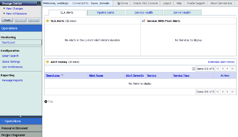
Click Create in the Change Center area to start a new Oracle Service Bus session, as shown in Figure 7-54.
Click Project Explorer in the left pane, as shown in Figure 7-55.
The Project Explorer page is displayed, as shown in Figure 7-56.
Provide a valid name for the new project (for example, JDE_Project) and click Add Project.
The project is successfully created and listed.
Click on the created project.
The project page is displayed, as shown in Figure 7-57.
In the Enter New Folder Name field, type Business Service and click Add Folder.
In the Enter New Folder Name field, type Proxy Service and click Add Folder.
In the Enter New Folder Name field, type wsdls and click Add Folder.
The Business Service, Proxy Service, and wsdls folders are listed in the left pane below the project node, as shown in Figure 7-58.
Before starting and using Application Explorer to publish a WSDL directly to the Oracle Service Bus (OSB) Console (project/folder), OSB users must perform the following steps:
Open the command prompt window.
Navigate to the following directory:
<OSB_Home>\user_projects\domains\base_domain\bin
Execute setDomainEnv.cmd (Windows) or . ./setDomainEnv.sh (UNIX/Linux).
This command sets the class path for Application Explorer to access the Oracle WebLogic Server APIs to publish the WSDLs to the OSB Console.
Do not close the command prompt window.
Navigate to the following directory:
<OSB_Home>\3rdparty\ApplicationAdapters\tools\iwae\bin
Execute ae.bat (Windows) or iwae.sh (UNIX/Linux) to start Application Explorer.
You are now ready to publish WSDLs from Application Explorer to the OSB Console.
Before you publish a WSDL from Application Explorer to Oracle Service Bus, you must create a separate channel for every J2CA event and select that channel when you generate WSDL for inbound interaction using Application Explorer.
Creating a Channel in Application Explorer
To create a channel:
In Application Explorer, connect to a J2CA configuration.
Expand the Events node and then the JDEdwards node, as shown in Figure 7-59.
Figure 7-59 Application Explorer Add Channel Option
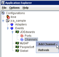
Right-click the Channels node, and select Add Channels.
The Add Channel dialog is displayed, as shown in Figure 7-60.
In the Name field, enter a descriptive name for the channel.
In the Description field, enter a description (optional).
From the Protocol list, choose a protocol for your channel.
Click Next.
The dialog is displayed for the selected listener, as shown in Figure 7-61.
Enter the port number of the channel in the Port Number field.
Enter the location of the server in the Host/IP Binding field.
Select the Synchronization type from the Synchronization Type list.
Select Is Length Prefix for events that send data which is not in XML format. The TCP/IP event application must prefix the data with a 4-byte binary length field when writing the data to the TCP/IP port.
Select Is XML for events that send data back in XML format. No preparser is required.
Select Is Keep Alive to maintain a continuous communication between the event transaction and the channel.
Click the PreParser tab, as shown in Figure 7-62.
Enter values based on the table.
| Parameter | Description |
|---|---|
| User id* | A valid user ID for J.D. Edwards OneWorld. |
| User password* | The password associated with the user ID. |
| JDE environment* | Your J.D. Edwards OneWorld environment. For more information about this parameter, see your J.D. Edwards OneWorld documentation or ask your OneWorld system administrator. |
| Application | XMLInterop or the application name in J.D. Edwards OneWorld. Optional. |
| Server IP address* | The name of the server on which J.D. Edwards OneWorld is running. This can be the name of the server, for example, JDEOW, or its IP address, for example, 123.45.67.89. |
| Server Port* | The port number on which the server is listening, for example, 6009. |
| User Role | Define a user role according to your requirements. |
| Schema Location | The location of the XML schema (.xsd file) that was generated from the event output. For example:
<OSB_Home>\3rdparty\ApplicationAdapters\config\config_name\schemas\JDEdwards\target_name\jde-schema.xsd |
| Schema style | Choose from one of the following options:
|
Click OK.
The channel is created and displayed under the Channels node. An X over the icon indicates that the channel is currently disconnected.
Generating WSDL for Event Notification (Command Prompt Only)
You cannot generate WSDL for J.D. Edwards OneWorld event notification using Application Explorer. To generate WSDL from the command prompt, you must perform the following steps.
You can create inbound J2CA service only if the node you have selected supports events.
Note:
The schema validation options (Root, Namespace, Schema) are not applicable for the Oracle Application Adapter for J.D. Edwards OneWorld.To generate a WSDL file for J.D. Edwards OneWorld event notification:
Create a channel in Application Explorer under the J.D. Edwards events node.
Start the channel.
Important: Do not restart the Oracle Application Server after the channel is started.
Send an inbound message from J.D. Edwards OneWorld.
Capture the inbound message payload in the log file located under:
<OSB_Home>\3rdparty\ApplicationAdapters\config\jca_sample\log\iwaf_jca1500.log
Alternatively, you can create a port with the File protocol under Event in Application Explorer to dispose the event message to the file system.
Use a third party tool such as XMLSpy to create the XSD schema using the XML payload captured in the previous step.
In the generated XML schema (.xsd file) perform the following modifications:
Search for Schemas-jdedwards-com and replace it with iwaysoftware.
Cut the following syntax:
<xs:element name="jdeResponse"><xs:complexType> </xs:complexType> </xs:element>
Paste it before the following line:
<xs:element name="transaction">
Copy the XML schema (.xsd file) from the following directory:
<OSB_Home>\3rdparty\ApplicationAdapters\config\config_name\schemas\JDEdwards\target_name\
Note:
Edit the created channel by providing the location of the schema (.xsd) file (as mentioned in step 7) in the PreParser tab of Application Explorer. For example:<OSB_Home>\3rdparty\ApplicationAdapters\config\config_name\schemas\JDEdwards\target_name\jde-schema.xsd
Open a command prompt and navigate to the following directory:
<OSB_Home>\3rdparty\ApplicationAdapters\tools\iwae\bin
Execute the obadapter.bat file to set the environment.
Navigate to the following directory where the XML schema (.xsd file) is copied:
<OSB_Home>\3rdparty\ApplicationAdapters\config\config_name\schemas\JDEdwards\target_name\
Enter the following command to generate a WSDL:
java -Diway.oem=oracle11g com.iwaysoftware.af.container.tools.wsdl.IWayWSILBrowser adapterhome adapter target channel schemaPrefix wsdlFileName
where:
adapterhome is the path to your ApplicationAdapters home. For example:
<OSB_Home>\3rdparty\ApplicationAdapters\
adapter is the name of the adapter. For example, JDEdwards.
target is the name of the adapter target you created in Application Explorer.
channel is the name of the channel you created in Application Explorer.
schemaPrefix is the prefix for the XSD schema. The schema file must be in the same directory where the Java command is executed, for example:
java -Diway.oem=oracle11g com.iwaysoftware.af.container.tools.wsdl.IWayWSILBrowser C:\OSBPS3\Oracle_OSB1\3rdparty\ApplicationAdapters\wsdls\JDEdwards jde812_tgt jde_ch Jde812_Schema Jde812_salesorder_receive.wsdl
Once the command is executed, the following is displayed in the command window:
Running Inbound WSDL generation tool...-> user.dir = java com.iwaysoftware.af.container.tools.wsdl.IWayWSILBrowser C:\OSBPS3\Oracle_OSB1\3rdparty\wsdls\ApplicationAdapters\JDEdwards jde812_tgt jde_ch Jde812_Schema Jde812_salesorder_receive.wsdl -> Generating WSDL...-> Done.-> Writing WSDL 'C:\OSBPS3\Oracle_OSB1\3rdparty\ApplicationAdapters\wsdls\Jde812_salesorder_receive.wsdl ' to disk...-> Done.
Note:
It is good practice to append _receive to the names of WSDL files that are generated for event notification services. This allows you to easily distinguish between them and those generated for request-response services.Stop the channel in Application Explorer.
Note:
You can organize your WSDL files in subfolders, creating your own WSDL hierarchy structure. Create the folders under<OSB_Home>\3rdparty\ApplicationAdapters\wsdls. The WSIL browser in Oracle JDeveloper displays the full tree structure of your WSDL hierarchy.Once you have generated the inbound WSDL for J.D. Edwards OneWorld, you must import the inbound WSDL file into Oracle Service Bus.
Open the Oracle Service Bus Console and select the created WSDL folder in the left pane (for example, wsdls), as shown in Figure 7-63.
In the right pane, select XML Schema from the Create Resource menu.
The Create a New XML Schema Resource page is displayed, as shown in Figure 7-64.
Figure 7-64 Create a New XML Schema Resource Page
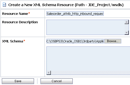
Enter a name for the inbound XML schema in the Resource Name field.
You can also provide a brief description for the resource (optional).
Using the Browse option in the XML Schema field, navigate to the location of the inbound XML schema file (.xsd) on your file system.
Click Save.
The inbound XML schema is added to the OSB console, as shown in Figure 7-65.
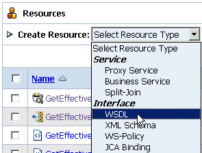
In the right pane, select WSDL from the Create Resource menu, as shown in Figure 7-66.
Figure 7-66 Create Resource Menu WSDL Option
The Create a New WSDL Resource page is displayed, as shown in Figure 7-67.
Figure 7-67 Create a New WSDL Resource Page
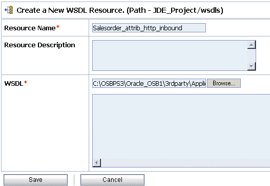
Enter a name for the inbound WSDL in the Resource Name field.
You can also provide a brief description for the resource (optional).
Using the Browse option in the WSDL field, navigate to the location of the inbound WSDL file (.wsdl) on your file system.
Click Save.
The inbound WSDL is added to the OSB console, as shown in Figure 7-68.
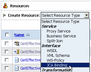
In the right pane, select JCA Binding from the Create Resource menu, as shown in Figure 7-69.
Figure 7-69 Create Resource Menu JCA Binding Option
The Create a New JCA Binding Resource page is displayed, as shown in Figure 7-70.
Figure 7-70 Create a New JCA Binding Resource Page
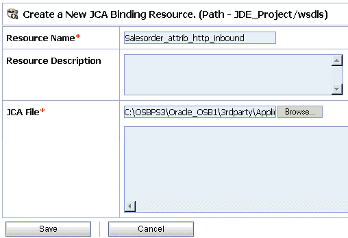
Enter a name for the inbound JCA binding in the Resource Name field.
You can also provide a brief description for the resource (optional).
Using the Browse option in the JCA File field, navigate to the location of the inbound JCA binding file (.jca) on your file system.
Click Save.
The inbound JCA binding is added to the OSB console, as shown in Figure 7-71.
Click the icon that corresponds to the exported WSDL in the Actions column, as shown in Figure 7-72.
The Generate WSDL and Service page is displayed.
Provide a new WSDL name and a new service name in the corresponding fields, as shown in Figure 7-73.
Figure 7-73 Generate WSDL and Service Page
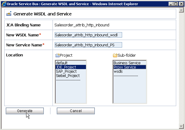
In the Location area, select an available project and the sub-folder that is designated for Proxy Services.
Click Generate.
If the WSDL and Service resources are successfully created, then the following message is displayed, as shown in Figure 7-74.
Select the Proxy Service folder you created in the left pane and verify that the Proxy Service is successfully generated and listed, as shown in Figure 7-75.
Perform the following steps to configure a File type Business Service:
Select the Business Service folder you created in the left pane, as shown in Figure 7-76.
In the right pane, select Business Service from the Create Resource menu, as shown in Figure 7-77.
The General Configuration page is displayed, as shown in Figure 7-78.
Provide a name for the Business Service and from the Service Type area select Messaging Service.
Click Next.
The Message Type Configuration page is displayed, as shown in Figure 7-79.
Figure 7-79 Message Type Configuration page
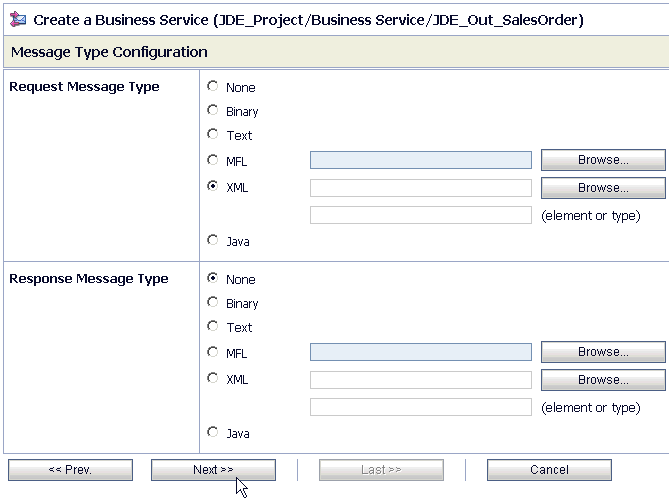
Select XML as the Request Message Type and None as the Response Message Type.
Click Next.
The Transport Configuration page is displayed, as shown in Figure 7-80.
Select file from the Protocol list.
Enter the path to a destination folder on your file system in the Endpoint URI field and click Add.
Click Next.
The FILE Transport Configuration page is displayed, as shown in Figure 7-81.
Figure 7-81 FILE Transport Configuration Page

Enter the prefix and suffix for the output file to be received and click Next.
The Message Handling and Advanced Settings page is displayed, as shown in Figure 7-82.
Figure 7-82 Message Handling and Advanced Settings Page

Click Next.
The following Summary page is displayed, as shown in Figure 7-83.
Review all the information for your Business Service and click Save.
Check if the success message is displayed and click Activate in the Change Center, as shown in Figure 7-84.
Figure 7-84 Change Center Activate Button

The Activate Session page is displayed, as shown in Figure 7-85.
Click Submit.
Check if the View Configuration Changes page is displayed.
Figure 7-86 View Configuration Changes Page

Perform the following steps to configure a Pipeline:
Click the Edit Message Flow icon in the row of the Proxy Service you created, as shown in Figure 7-87.
The Edit Message Flow workspace area is displayed, as shown in Figure 7-88.
Figure 7-88 Edit Message Flow Workspace Area
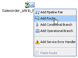
Click the displayed Proxy service icon and select Add Route from the menu.
The RouteNode1 icon is added below the Request Pipeline icon, as shown in Figure 7-89.
Figure 7-89 Edit Message Flow Edit Route Option
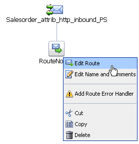
Click the RouteNode1 icon and select Edit Route from the menu.
The Edit Stage Configuration workspace area is displayed, as shown in Figure 7-90.
Figure 7-90 Edit Stage Configuration Routing Option

Click Add an Action, select Communication from the menu, and click Routing, as shown in Figure 7-91.
Figure 7-91 Edit Stage Configuration Page

Click <Service>.
The Select Service dialog is displayed, as shown in Figure 7-92.
Select a WSDL type Business Service and click Submit.
You are returned to the Edit Stage Configuration workspace area, as shown in Figure 7-93.
Figure 7-93 Edit Stage Configuration Workspace Area
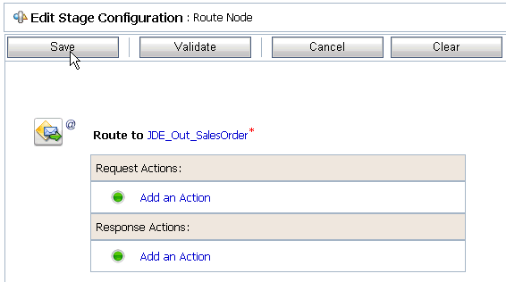
Click Save.
You are returned to the Edit Message Flow workspace area, as shown in Figure 7-94.
Figure 7-94 Edit Message Flow Workspace Area

Click Save, as shown in Figure 7-95.
Check if the success message is displayed and click Activate in the Change Center.
The Activate Session page is displayed as shown in Figure 7-96.
Click Submit.
Check if the View Configuration Changes page is displayed, as shown in Figure 7-97.
Figure 7-97 View Configuration Changes Page

Trigger an event from the J.D. Edwards OneWorld system and check if the output is received in the configured output location.
This section describes how to configure outbound processing using Oracle Service Bus for BSE configurations.
This section includes the following topics:
Setting the Class Path for Application Explorer to Integrate With Oracle Service Bus
Publishing a WSDL From Application Explorer to Oracle Service Bus
Perform the following steps to start Oracle Service Bus and create project folders:
Start the Oracle WebLogic Server for the Oracle WebLogic Server domain that you have configured.
Open the Oracle Service Bus Console in a Web browser by entering the following URL:
http://hostname:port/sbconsole
Where hostname is the name of the machine where Oracle WebLogic Server is running and port is the port for the domain you are using. The port for the default domain is 7001.
The Oracle Service Bus Console logon page is displayed.
Log on to the Oracle Service Bus Console using a valid user name and password.
The Oracle Service Bus Console home page is displayed, as shown in Figure 7-98.
Figure 7-98 Oracle Service Bus Console Home Page

Click Create in the Change Center area to start a new Oracle Service Bus session, as shown in Figure 7-99.
Click Project Explorer in the left pane, as shown in Figure 7-100.
The Project Explorer page is displayed, as shown in Figure 7-101.
Provide a valid name for the new project (for example, JDE_Project) and click Add Project.
The project is successfully created and listed.
Click on the created project.
The project page is displayed, as shown in Figure 7-102.
In the Enter New Folder Name field, type Business Service and click Add Folder.
In the Enter New Folder Name field, type Proxy Service and click Add Folder.
In the Enter New Folder Name field, type wsdls and click Add Folder.
The Business Service, Proxy Service, and wsdls folders are listed in the left pane below the project node, as shown in Figure 7-103.
Before starting and using Application Explorer to publish a WSDL directly to the Oracle Service Bus (OSB) Console (project/folder), OSB users must perform the following steps:
Open the command prompt window.
Navigate to the following directory:
<OSB_Home>\user_projects\domains\base_domain\bin
Execute setDomainEnv.cmd (Windows) or . ./setDomainEnv.sh (UNIX/Linux).
This command sets the class path for Application Explorer to access the Oracle WebLogic Server APIs to publish the WSDLs to the OSB Console.
Do not close the command prompt window.
Navigate to the following directory:
<OSB_Home>\3rdparty\ApplicationAdapters\tools\iwae\bin
Execute ae.bat (Windows) or iwae.sh (UNIX/Linux) to start Application Explorer.
You are now ready to publish WSDLs from Application Explorer to the OSB Console.
This section describes how to publish a WSDL from Application Explorer (BSE configuration) to Oracle Service Bus.
Start Application Explorer, connect to a BSE configuration, and connect to a J.D. Edwards target, as shown in Figure 7-104.
Figure 7-104 Application Explorer Create Web Service Option
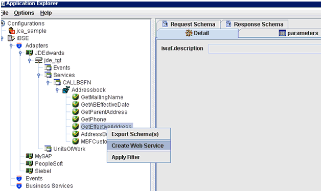
Expand the Services node, followed by CALLBSFN and Addressbook.
Right-click the GetEffectiveAddress business object and select Create Web Service from the menu.
The Create Web Service dialog is displayed, as shown in Figure 7-105.
Enter a service name and click Next.
Click OK on the next dialog that is displayed.
Application Explorer switches the view to the Business Services node, and the new Web service appears in the left pane, as shown in Figure 7-106.
Figure 7-106 Application Explorer Export WSDL Option
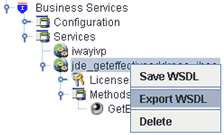
Right-click the new Web service and select Export WSDL from the menu.
The Export WSDL dialog is displayed, as shown in Figure 7-107.
In the Name field, a default file name for the WSDL file is provided. You can accept the default or provide your own.
In the Location field, enter the location where you want to publish the WSDL document.
The location is composed of an Oracle Service Bus project name and optionally, one or more folder names. The project name and any folder names must be separated by a forward slash character “/”.
In the Host field, enter the name of the machine where Oracle WebLogic Server is running.
In the Port field, enter the port for the domain you are using.
In the User field, enter your username to access Oracle Service Bus.
In the Password field, enter your password to access Oracle Service Bus.
Click OK.
The WSDL is published to the location specified in the Export WSDL dialog and is now available for use with a Business Service or Proxy Service in Oracle Service Bus.
This section describes how to configure a File type Business Service using the Oracle Service Bus Console.
Select the Business Service folder you created in the left pane, as shown in Figure 7-108.
In the right pane, select Business Service from the Create Resource menu.
The General Configuration page is displayed, as shown in Figure 7-109.
Provide a name for the Business Service and from the Service Type area select Messaging Service.
Click Next.
The Message Type Configuration page is displayed, as shown in Figure 7-110.
Figure 7-110 Message Type Configuration Page
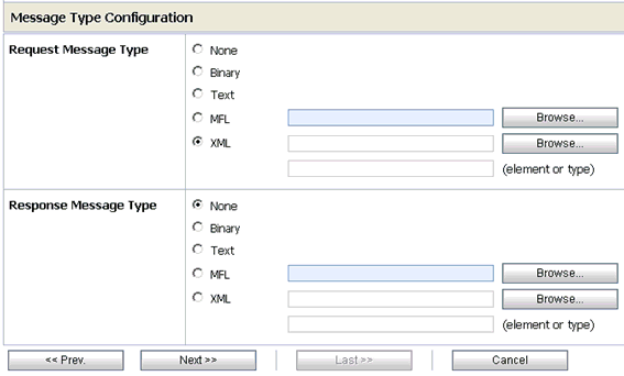
Select XML as the Request Message Type and None as the Response Message Type.
Click Next.
The Transport Configuration page is displayed, as shown in Figure 7-111.
Figure 7-111 Transport Configuration Page
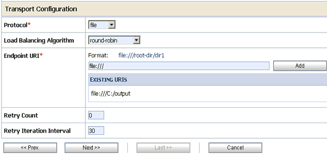
Select file from the Protocol list.
Enter the path to a destination folder on your file system in the Endpoint URI field and click Add.
Click Next.
The FILE Transport Configuration page is displayed, as shown in Figure 7-112.
Figure 7-112 FILE Transport Configuration Page

Enter the prefix and suffix for the output file to be received and click Next.
The Summary page is displayed, as shown in Figure 7-113.
Review all the information for your Business Service and click Save.
This section describes how to configure a WSDL type Business Service using the Oracle Service Bus Console.
Select the Business Service folder you created in the left pane, as shown in Figure 7-114.
In the right pane, select Business Service from the Create Resource menu.
The General Configuration page is displayed, as shown in Figure 7-115.
Provide a name for the Business Service and from the Service Type area select WSDL Web Service.
Click Browse.
The Select a WSDL dialog is displayed, as shown in Figure 7-116.
Select a BSE WSDL that you published for Oracle Application Adapter for J.D. Edwards OneWorld using Application Explorer and click Submit.
The Select a WSDL Definition dialog is displayed, as shown in Figure 7-117.
Figure 7-117 Select a WSDL Definition Dialog
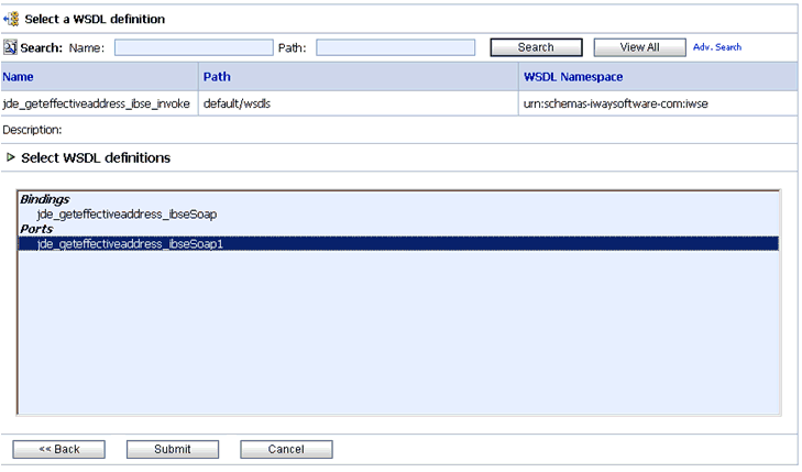
Select the WSDL definition under the Ports section and click Submit.
You are returned to the General Configuration page where the WSDL you selected is now available.
Click Next.
The Transport Configuration page is displayed, as shown in Figure 7-118.
Figure 7-118 Transport Configuration Page
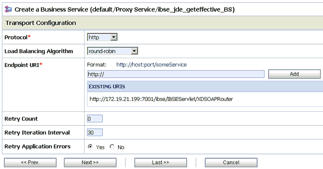
Leave the default values and click Next.
The HTTP Transport Configuration page is displayed, as shown in Figure 7-119.
Figure 7-119 HTTP Transport Configuration Page
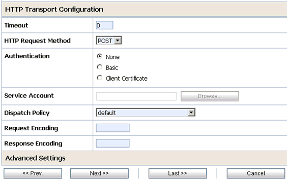
Leave the default values and click Next.
The SOAP Binding Configuration page is displayed, as shown in Figure 7-120.
Figure 7-120 SOAP Binding Configuration Page

Click Next.
The Message Content Handling page is displayed, as shown in Figure 7-121.
Figure 7-121 Message Content Handling Page

Click Next.
The Summary page is displayed, as shown in Figure 7-122.
Review all the information for your Business Service and click Save.
This section describes how to configure a Proxy Service using the Oracle Service Bus Console.
Select the Proxy Service folder you created in the left pane, as shown in Figure 7-123.
In the right pane, select Proxy Service from the Create Resource menu.
The General Configuration page is displayed, as shown in Figure 7-124.
Provide a name for the Proxy Service and from the Service Type area select Any XML Service.
Click Next.
The Transport Configuration page is displayed, as shown in Figure 7-125.
Figure 7-125 Transport Configuration Page
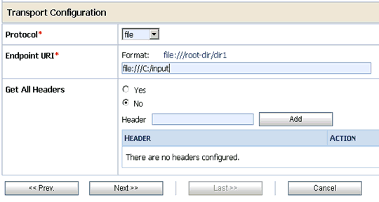
Select file from the Protocol list.
Enter the path to an input folder on your file system in the Endpoint URI field.
Click Next.
The FILE Transport Configuration page is displayed, as shown in Figure 7-126.
Figure 7-126 FILE Transport Configuration Page
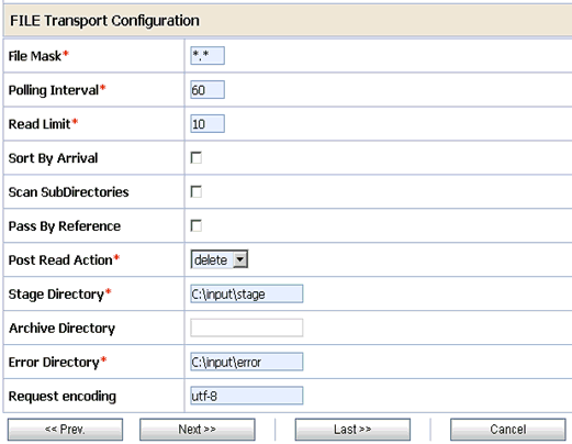
Provide any folder locations on your file system for the Stage Directory and Error Directory fields.
Click Next.
The Message Content Handling page is displayed, as shown in Figure 7-127.
Figure 7-127 Message Content Handling Page
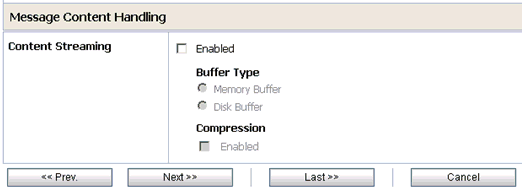
Click Next.
The Summary page is displayed, as shown in Figure 7-128.
Review all the information for your Proxy Service and click Save.
This section describes how to configure a Pipeline using the Oracle Service Bus Console.
Click the Edit Message Flow icon in the row of the Proxy Service you created, as shown in Figure 7-129.
The Edit Message Flow workspace area is displayed.
Click the Proxy Service icon and select Add Pipeline Pair from the menu, as shown in the following image, as shown in Figure 7-130.
Click the Request Pipeline icon and select Add Stage from the menu, as shown in Figure 7-131.
The Stage1 icon is added below the Request Pipeline icon, as shown in Figure 7-132.
Click the Stage1 icon and select Edit Stage from the menu.
The Edit Stage Configuration workspace area is displayed, as shown in Figure 7-133.
Figure 7-133 Edit Stage Configuration Workspace Area
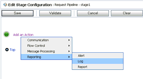
Click Add an Action, select Reporting from the menu, and click Log, as shown in Figure 7-134.
Figure 7-134 Edit Stage Configuration Workspace Area
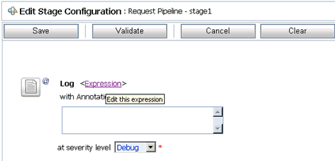
Click <Expression> to edit the expression.
The XQuery/XSLT Expression Editor is displayed, as shown in Figure 7-135.
Figure 7-135 XQuery/XSLT Expression Editor
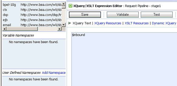
In the XQuery Text area, type $inbound.
Click Validate and then Save.
You are returned to the Edit Stage Configuration workspace area, as shown in Figure 7-136.
Figure 7-136 Edit Stage Configuration Workspace Area
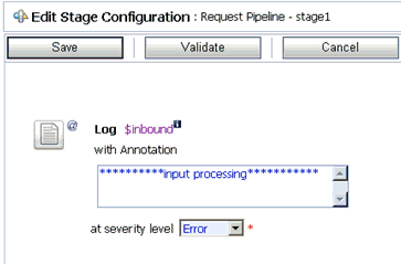
Type any annotation/comments in the text box (for example, **********input processing***********).
Select Error from the severity level list.
Add one more Log action as shown in the following image, as shown in Figure 7-137.
Figure 7-137 Edit Stage Configuration Workspace Area
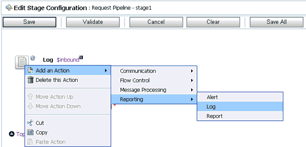
A new Log configuration is added, as shown in the following image, as shown in Figure 7-138.
Figure 7-138 Edit Stage Configuration Workspace Area
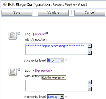
Click <Expression> to edit the expression.
The XQuery/XSLT Expression Editor is displayed, as shown in Figure 7-139.
Figure 7-139 XQuery/XSLT Expression Editor
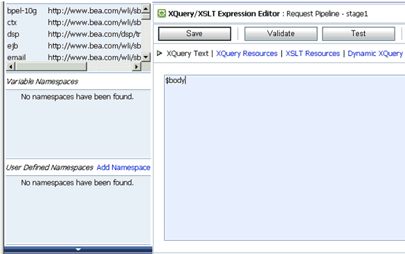
In the XQuery Text area, type $body.
Click Validate and then Save.
You are returned to the Edit Stage Configuration workspace area, as shown in Figure 7-140.
Figure 7-140 Edit Stage Configuration Workspace Area
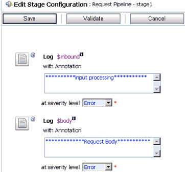
Type any annotation/comments in the text box (for example, **********Request Body***********).
Select Error from the severity level list.
Click Validate and then Save, as shown in Figure 7-141.
Click the PipelinePairNode1 icon and select Add Route from the menu, as shown in Figure 7-142.
Click the RouteNode1 icon and select Edit Route from the menu, as shown in Figure 7-143.
Figure 7-143 Edit Stage Configuration Routing Option
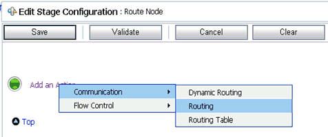
Click Add an Action, select Communication from the menu, and click Routing, as shown in Figure 7-144.
Figure 7-144 Edit Stage Configuration Workspace Area
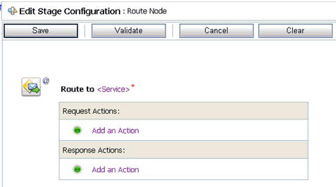
Click <Service>.
The Select Service dialog is displayed, as shown in Figure 7-145.
Select a WSDL type Business Service and click Submit.
You are returned to the Edit Stage Configuration workspace area, as shown in Figure 7-146.
Figure 7-146 Edit Stage Configuration Workspace Area
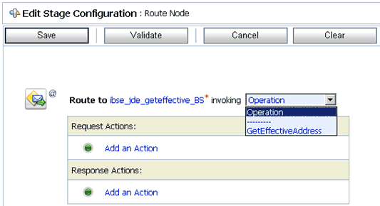
Select GetEffectiveAddress as the operational attribute from the list.
Click Validate and then Save, as shown in Figure 7-147.
Figure 7-147 Edit Stage Configuration Workspace Area
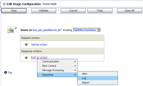
In the Response Actions area, click Add an Action, select Reporting from the menu, and click Log.
Click <Expression> to edit the expression.
The XQuery/XSLT Expression Editor is displayed, as shown in Figure 7-148.
Figure 7-148 XQuery/XSLT Expression Editor

In the XQuery Text area, type $outbound.
Click Validate and then Save.
You are returned to the Edit Stage Configuration workspace area, as shown in Figure 7-149.
Figure 7-149 Edit Stage Configuration Workspace Area
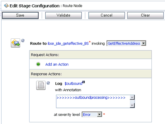
Type any annotation/comments in the text box (for example, **********output processing***********).
Select Error from the severity level list.
Click Validate and then Save, as shown in Figure 7-150.
Click the Response Pipeline icon and select Add Stage from the menu.
The Stage1 icon is added below the Response Pipeline icon, as shown in Figure 7-151.
Click the Stage1 icon and select Edit Stage from the menu.
The Edit Stage Configuration workspace area is displayed, as shown in Figure 7-152.
Figure 7-152 Edit Stage Configuration Workspace Area
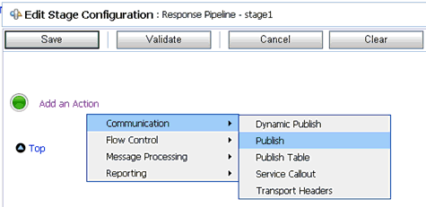
Click Add an Action, select Communication from the menu, and click Publish, as shown in Figure 7-153.
Figure 7-153 Edit Stage Configuration Workspace Area
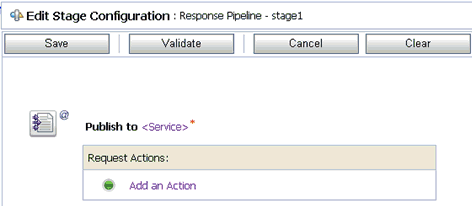
Click <Service>.
The Select Service dialog is displayed, as shown in Figure 7-154.
Select a File type Business Service and click Submit.
You are returned to the Edit Stage Configuration workspace area, as shown in Figure 7-155.
Figure 7-155 Edit Stage Configuration Workspace Area
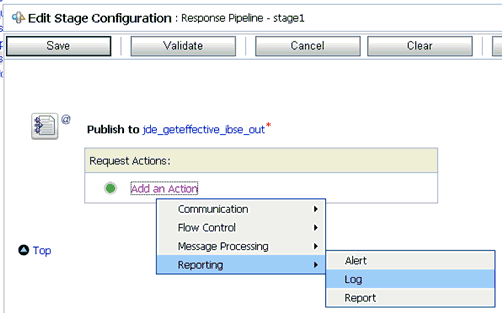
In the Request Actions area, click Add an Action, select Reporting from the menu, and click Log, as shown in Figure 7-156.
Figure 7-156 Edit Stage Configuration Workspace Area
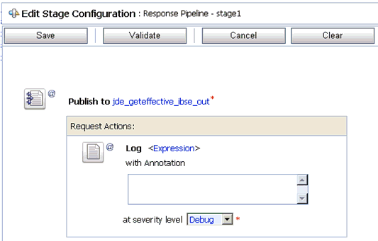
Click <Expression> to edit the expression.
The XQuery/XSLT Expression Editor is displayed, as shown in Figure 7-157.
Figure 7-157 XQuery/XSLT Expression Editor
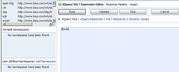
In the XQuery Text area, type $body.
Click Validate and then Save.
You are returned to the Edit Stage Configuration workspace area, as shown in Figure 7-158.
Figure 7-158 Edit Stage Configuration Workspace Area
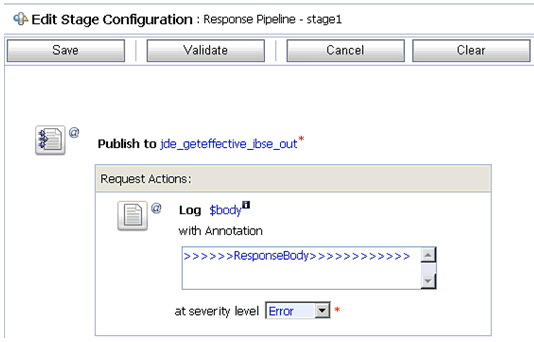
Type any annotation/comments in the text box (for example, **********Response Body***********).
Select Error from the severity level list.
Click Validate and then Save.
The completed Pipeline is displayed, as shown in Figure 7-159.
Click Save.
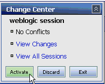
Click Activate in the Change Center area to activate your changes in the Oracle Service Bus session, as shown in Figure 7-160.
Figure 7-160 Change Center Activate Button
Copy and paste an input XML file in the input folder you have configured, as shown in Figure 7-161.
An output XML file is received in the destination folder, as shown in Figure 7-162.
Figure 7-162 Output XML Destination Folder
