| Oracle® Fusion Middleware Administrator's Guide for Oracle Web Cache 11g Release 1 (11.1.1) Part Number E10143-04 |
|
|
View PDF |
| Oracle® Fusion Middleware Administrator's Guide for Oracle Web Cache 11g Release 1 (11.1.1) Part Number E10143-04 |
|
|
View PDF |
This chapter describes how to configure common deployment scenarios using Oracle Web Cache. It includes the following topics:
Section 10.1, "Using Oracle Web Cache in a Common Deployment"
Section 10.2, "Using a Cache Hierarchy for a Global Intranet Application"
Section 10.3, "Using Oracle Web Cache for High Availability without a Hardware Load Balancer"
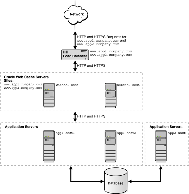
Figure 10-1 shows Oracle Web Cache in a common Oracle Application Server configuration. A tier of Oracle Web Cache servers cache content for a tier of application Web servers. The application Web servers app1-host1 and app1-host2 provide content for site www.app1.company.com, and app2-host provides content for www.app2.company.com. The two Oracle Web Cache servers reside on dedicated, fast one or two-CPU computers. To increase the availability and capacity of a Web site, these servers are configured as either a cache cluster or a failover pair.
Oracle recommends a hardware load balancer to ping each Oracle Web Cache server on a periodic basis to check the status of the cache.
As a cache cluster, the two Oracle Web Cache servers provide failure detection and failover. If an Oracle Web Cache server fails, other members of the cache cluster detect the failure and take over ownership of the cached content of the failed cluster member and masks any cache failure. Oracle Web Cache maintains a virtual single cache of content despite a cache failure. The load balancer distributes the incoming requests among cache cluster members. The cache cluster members process the incoming requests. For requests that are not stored in the cache, Oracle Web Cache distributes the requests to an application Web server respective to the site.
As a failover pair, both Oracle Web Cache servers are configured to cache the same content. When both Oracle Web Cache servers are running, a load balancer distributes the load among both servers. If one server fails, the other server receives and processes all incoming requests.
Figure 10-1 Deploying Oracle Web Cache In a Common Configuration

To configure this topology:
Register the IP address of the load balancer with www.app1.company.com and www.app2.company.com.
Configure the load balancer with Oracle Web Cache server host names webche1-host and webche2-host and configure it to ping each cache server periodically to check the status of the cache.
Configure the load balancer with to ping each Oracle Web Cache server on a periodic basis with URL /_oracle_http_server_webcache_static_.html, which is stored in the cache.
If configuring a cache cluster, specify webche1-host and webche2-host as cluster members.
See Section 3.6 for more information on configuring a cache cluster.
Configure the Oracle Web Cache servers with the following:
Receive HTTP and HTTPS requests on designated listening ports
Send HTTP and HTTPS requests to application Web servers app1-host1, app1-host2, and app2-host on designated listening ports
Site definition for www.app1.company.com mapped to app1-host1 and app1-host2
Site definition for www.app2.company.com mapped to app2-host
For more information, see:
Section 2.11.1 for instructions about configuring listening ports
Section 2.11.2 for instructions about configuring origin server settings
Section 2.11.3 for instructions on creating site definitions and site-to-server mappings
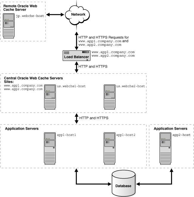
Many Web sites have several data centers. For networks with a distributed topology, you can deploy Oracle Web Cache at each of the data centers in a distributed cache hierarchy. Figure 10-2 shows a distributed topology in which Oracle Web Cache servers are distributed in offices in the United States and Japan. The application Web servers are located in the United States office, centralizing the data source to one geographic location. The central caches in the United States cache content for application Web servers app1-host1, app2-host2, and app2-host, and the remote cache in Japan caches content from the central caches.
Clients make requests to local DNS servers to resolve www.app1.company.com and www.app2.company.com. The local DNS servers are routed to the authoritative DNS server for the respective sites. The authoritative DNS server uses the IP address of the client to pick the closest Oracle Web Cache server to satisfy the request. Then, it returns the IP address of the appropriate Oracle Web Cache server to the client.
Figure 10-2 Deploying an Oracle Web Cache Hierarchy

To configure this topology:
Register the IP address of the load balancer with www.app1.company.com and www.app2.company.com.
Configure the load balancer with Oracle Web Cache server host names us.webche1-host and us.webche2-host and configure it to ping each cache server periodically to check the status of the cache.
Configure Oracle Web Cache servers us.webche1-host and us.webche1-host with the following:
Receive HTTP and HTTPS requests on designated listening ports
Send HTTP and HTTPS requests to application Web servers app1-host1, app1-host2, and app2-host on designated listening ports
Site definition for www.app1.company.com mapped to app1-host1 and app1-host2
Site definition for www.app2.company.com mapped to app2-host
Configure Oracle Web Cache server jp.webche-host with the following:
Receive HTTP and HTTPS requests on designated listening ports
Send HTTP and HTTPS requests to application Web servers us.webche1-host and us.webche2-host on designated listening ports
Site definition for www.app1.company.com mapped to app1-host1 and app1-host2
Site definition for www.app2.company.com mapped to app2-host
Enable propagation of invalidation messages for each of the caches in the cache hierarchy:
Use a text editor to open webcache.xml, located in:
(UNIX) ORACLE_INSTANCE/<instance_name>/config/WebCache/<webcache_name>
(Windows) ORACLE_INSTANCE\<instance_name>\config\WebCache\<webcache_name>
Locate the <INTERCACHE> element, a sub-element of the <SECURITY> element.
Modify the ENABLEINBOUNDICC and ENABLEOUTBOUNDICC attributes to YES. For example:
<?xml version="1.0" encoding='ISO-8859-1'?>
<CALYPSO ... >
 <VERSION DTD_VERSION="11.1.1.0.0"/>
 <GENERAL>
   <CLUSTER NAME="WebCacheCluster" ... />
   <SECURITY SSLSESSIONTIMEOUT="3600" ... >
     <USER TYPE="INVALIDATION" ... />
     <USER TYPE="MONITORING" ... />
     <SECURESUBNET ALLOW="ALL"/>
     <DEBUGINFO HEADER="YES" ... />
     <HTTPREQUEST MAXTOTALHEADERSIZE="819000" ... />
     <INTERCACHE ENABLEINBOUNDICC="YES" ENABLEOUTBOUNDICC="YES"/>
   </SECURITY>
...
Save webcache.xml.
Restart the caches in the hierarchy with the following command:
opmnctl restartproc ias-component=component_name
This executable is found in the following directory:
(UNIX) ORACLE_INSTANCE/bin
(Windows) ORACLE_INSTANCE\bin
For more information, see:
Section 2.11.1 for instructions about configuring listening ports
Section 2.11.2 for instructions about configuring origin server settings
Section 2.11.3 for instructions on creating site definitions and site-to-server mappings
Section 7.10.2.2 to understand how invalidation in a hierarchy works
You can make Oracle Web Cache highly available without a hardware load balancer by configuring:
Oracle Web Cache solely as a software load balancer of HTTP traffic or reverse proxy to origin servers
With this option, you configure one or more caches solely to provide load balancing or reverse proxy support.
Operating system load balancing capabilities
With this option, you configure the operating system to load-balance incoming requests across multiple caches. When the operating system detects a failure of one caches, automatic IP takeover is used to distribute the load to the remaining caches in the cluster configuration. This feature is supported on many operating systems, including Linux, Windows 2000 Advanced Server, Windows 2000 Datacenter Server, and Windows 2003 (all editions).
For more information, see Section 3.8 and Section 3.9 for configuration details.