Container Storage Interface (CSI) for Kubernetes Goes Beta


Kubernetes LogoCSI Logo

The Kubernetes implementation of the Container Storage Interface (CSI) is now beta in Kubernetes v1.10. CSI was introduced as alpha in Kubernetes v1.9.

Kubernetes features are generally introduced as alpha and moved to beta (and eventually to stable/GA) over subsequent Kubernetes releases. This process allows Kubernetes developers to get feedback, discover and fix issues, iterate on the designs, and deliver high quality, production grade features.

Why introduce Container Storage Interface in Kubernetes?

Although Kubernetes already provides a powerful volume plugin system that makes it easy to consume different types of block and file storage, adding support for new volume plugins has been challenging. Because volume plugins are currently “in-tree”—volume plugins are part of the core Kubernetes code and shipped with the core Kubernetes binaries—vendors wanting to add support for their storage system to Kubernetes (or even fix a bug in an existing volume plugin) must align themselves with the Kubernetes release process.

With the adoption of the Container Storage Interface, the Kubernetes volume layer becomes truly extensible. Third party storage developers can now write and deploy volume plugins exposing new storage systems in Kubernetes without ever having to touch the core Kubernetes code. This will result in even more options for the storage that backs Kubernetes users’ stateful containerized workloads.

What’s new in Beta?

With the promotion to beta CSI is now enabled by default on standard Kubernetes deployments instead of being opt-in.

The move of the Kubernetes implementation of CSI to beta also means:
* Kubernetes is compatible with v0.2 of the CSI spec (instead of v0.1)
* There were breaking changes between the CSI spec v0.1 and v0.2, so existing CSI drivers must be updated to be 0.2 compatible before use with Kubernetes 1.10.0+.
* Mount propagation, a feature that allows bidirectional mounts between containers and host (a requirement for containerized CSI drivers), has also moved to beta.
* The Kubernetes VolumeAttachment object, introduced in v1.9 in the storage v1alpha1 group, has been added to the storage v1beta1 group.
* The Kubernetes CSIPersistentVolumeSource object has been promoted to beta.
A VolumeAttributes field was added to Kubernetes CSIPersistentVolumeSource object (in alpha this was passed around via annotations).
* Node authorizer has been updated to limit access to VolumeAttachment objects from kubelet.
* The Kubernetes CSIPersistentVolumeSource object and the CSI external-provisioner have been modified to allow passing of secrets to the CSI volume plugin.
* The Kubernetes CSIPersistentVolumeSource has been modified to allow passing in filesystem type (previously always assumed to be ext4).
* A new optional call, NodeStageVolume, has been added to the CSI spec, and the Kubernetes CSI volume plugin has been modified to call NodeStageVolume during MountDevice (in alpha this step was a no-op).

How do I deploy a CSI driver on a Kubernetes Cluster?

CSI plugin authors must provide their own instructions for deploying their plugin on Kubernetes.

The Kubernetes-CSI implementation team created a sample hostpath CSI driver. The sample provides a rough idea of what the deployment process for a CSI driver looks like. Production drivers, however, would deploy node components via a DaemonSet and controller components via a StatefulSet rather than a single pod (for example, see the deployment files for the GCE PD driver).

How do I use a CSI Volume in my Kubernetes pod?

Assuming a CSI storage plugin is already deployed on your cluster, you can use it through the familiar Kubernetes storage primitives: PersistentVolumeClaims, PersistentVolumes, and StorageClasses.

CSI is a beta feature in Kubernetes v1.10. Although it is enabled by default, it may require the following flag:
* API server binary and kubelet binaries:
* –allow-privileged=true
* Most CSI plugins will require bidirectional mount propagation, which can only be enabled for privileged pods. Privileged pods are only permitted on clusters where this flag has been set to true (this is the default in some environments like GCE, GKE, and kubeadm).

Dynamic Provisioning

You can enable automatic creation/deletion of volumes for CSI Storage plugins that support dynamic provisioning by creating a StorageClass pointing to the CSI plugin.

The following StorageClass, for example, enables dynamic creation of “fast-storage” volumes by a CSI volume plugin called “com.example.csi-driver”.

kind: StorageClass
apiVersion: storage.k8s.io/v1
metadata:
name: fast-storage
provisioner: com.example.csi-driver
parameters:
type: pd-ssd
csiProvisionerSecretName: mysecret
csiProvisionerSecretNamespace: mynamespace

New for beta, the default CSI external-provisioner reserves the parameter keys csiProvisionerSecretName and csiProvisionerSecretNamespace. If specified, it fetches the secret and passes it to the CSI driver during provisioning.

Dynamic provisioning is triggered by the creation of a PersistentVolumeClaim object. The following PersistentVolumeClaim, for example, triggers dynamic provisioning using the StorageClass above.

apiVersion: v1
kind: PersistentVolumeClaim
metadata:
name: my-request-for-storage
spec:
accessModes:
– ReadWriteOnce
resources:
requests:
storage: 5Gi
storageClassName: fast-storage

When volume provisioning is invoked, the parameter type: pd-ssd and the secret any referenced secret(s) are passed to the CSI plugin com.example.csi-driver via a CreateVolume call. In response, the external volume plugin provisions a new volume and then automatically create a PersistentVolume object to represent the new volume. Kubernetes then binds the new PersistentVolume object to the PersistentVolumeClaim, making it ready to use.

If the fast-storage StorageClass is marked as “default”, there is no need to include the storageClassName in the PersistentVolumeClaim, it will be used by default.

Pre-Provisioned Volumes

You can always expose a pre-existing volume in Kubernetes by manually creating a PersistentVolume object to represent the existing volume. The following PersistentVolume, for example, exposes a volume with the name “existingVolumeName” belonging to a CSI storage plugin called “com.example.csi-driver”.

apiVersion: v1
kind: PersistentVolume
metadata:
name: my-manually-created-pv
spec:
capacity:
storage: 5Gi
accessModes:
– ReadWriteOnce
persistentVolumeReclaimPolicy: Retain
csi:
driver: com.example.csi-driver
volumeHandle: existingVolumeName
readOnly: false
fsType: ext4
volumeAttributes:
foo: bar
controllerPublishSecretRef:
name: mysecret1
namespace: mynamespace
nodeStageSecretRef:
name: mysecret2
namespace: mynamespace
nodePublishSecretRef
name: mysecret3
namespace: mynamespace

Attaching and Mounting

You can reference a PersistentVolumeClaim that is bound to a CSI volume in any pod or pod template.

kind: Pod
apiVersion: v1
metadata:
name: my-pod
spec:
containers:
– name: my-frontend
image: nginx
volumeMounts:
– mountPath: “/var/www/html”
name: my-csi-volume
volumes:
– name: my-csi-volume
persistentVolumeClaim:
claimName: my-request-for-storage

When the pod referencing a CSI volume is scheduled, Kubernetes will trigger the appropriate operations against the external CSI plugin (ControllerPublishVolume, NodeStageVolume, NodePublishVolume, etc.) to ensure the specified volume is attached, mounted, and ready to use by the containers in the pod.

For more details please see the CSI implementation design doc and documentation.

How do I write a CSI driver?

CSI Volume Driver deployments on Kubernetes must meet some minimum requirements.

The minimum requirements document also outlines the suggested mechanism for deploying an arbitrary containerized CSI driver on Kubernetes. This mechanism can be used by a Storage Provider to simplify deployment of containerized CSI compatible volume drivers on Kubernetes.

As part of the suggested deployment process, the Kubernetes team provides the following sidecar (helper) containers:
* external-attacher
* watches Kubernetes VolumeAttachment objects and triggers ControllerPublish and ControllerUnpublish operations against a CSI endpoint
* external-provisioner
* watches Kubernetes PersistentVolumeClaim objects and triggers CreateVolume and DeleteVolume operations against a CSI endpoint
* driver-registrar
* registers the CSI driver with kubelet (in the future) and adds the drivers custom NodeId (retrieved via GetNodeID call against the CSI endpoint) to an annotation on the Kubernetes Node API Object
* livenessprobe
* can be included in a CSI plugin pod to enable the Kubernetes Liveness Probe mechanism

Storage vendors can build Kubernetes deployments for their plugins using these components, while leaving their CSI driver completely unaware of Kubernetes.

Where can I find CSI drivers?

CSI drivers are developed and maintained by third parties. You can find a non-definitive list of some sample and production CSI drivers.

What about FlexVolumes?

As mentioned in the alpha release blog post, FlexVolume plugin was an earlier attempt to make the Kubernetes volume plugin system extensible. Although it enables third party storage vendors to write drivers “out-of-tree”, because it is an exec based API, FlexVolumes requires files for third party driver binaries (or scripts) to be copied to a special plugin directory on the root filesystem of every node (and, in some cases, master) machine. This requires a cluster admin to have write access to the host filesystem for each node and some external mechanism to ensure that the driver file is recreated if deleted, just to deploy a volume plugin.

In addition to being difficult to deploy, Flex did not address the pain of plugin dependencies: Volume plugins tend to have many external requirements (on mount and filesystem tools, for example). These dependencies are assumed to be available on the underlying host OS, which is often not the case.

CSI addresses these issues by not only enabling storage plugins to be developed out-of-tree, but also containerized and deployed via standard Kubernetes primitives.

If you still have questions about in-tree volumes vs CSI vs Flex, please see the Volume Plugin FAQ.

What will happen to the in-tree volume plugins?

Once CSI reaches stability, we plan to migrate most of the in-tree volume plugins to CSI. Stay tuned for more details as the Kubernetes CSI implementation approaches stable.

What are the limitations of beta?

The beta implementation of CSI has the following limitations:
* Block volumes are not supported; only file.
* CSI drivers must be deployed with the provided external-attacher sidecar plugin, even if they don’t implement ControllerPublishVolume.
* Topology awareness is not supported for CSI volumes, including the ability to share information about where a volume is provisioned (zone, regions, etc.) with the Kubernetes scheduler to allow it to make smarter scheduling decisions, and the ability for the Kubernetes scheduler or a cluster administrator or an application developer to specify where a volume should be provisioned.
* driver-registrar requires permissions to modify all Kubernetes node API objects which could result in a compromised node gaining the ability to do the same.

What’s next?

Depending on feedback and adoption, the Kubernetes team plans to push the CSI implementation to GA in 1.12.

The team would like to encourage storage vendors to start developing CSI drivers, deploying them on Kubernetes, and sharing feedback with the team via the Kubernetes Slack channel wg-csi, the Google group kubernetes-sig-storage-wg-csi, or any of the standard SIG storage communication channels.

How do I get involved?

This project, like all of Kubernetes, is the result of hard work by many contributors from diverse backgrounds working together.

In addition to the contributors who have been working on the Kubernetes implementation of CSI since alpha:
* Bradley Childs (childsb)
* Chakravarthy Nelluri (chakri-nelluri)
* Jan Šafránek (jsafrane)
* Luis Pabón (lpabon)
* Saad Ali (saad-ali)
* Vladimir Vivien (vladimirvivien)

We offer a huge thank you to the new contributors who stepped up this quarter to help the project reach beta:
* David Zhu (davidz627)
* Edison Xiang (edisonxiang)
* Felipe Musse (musse)
* Lin Ml (mlmhl)
* Lin Youchong (linyouchong)
* Pietro Menna (pietromenna)
* Serguei Bezverkhi (sbezverk)
* Xing Yang (xing-yang)
* Yuquan Ren (NickrenREN)

If you’re interested in getting involved with the design and development of CSI or any part of the Kubernetes Storage system, join the Kubernetes Storage Special Interest Group (SIG). We’re rapidly growing and always welcome new contributors.

Source

Continuous Delivery Pipeline with Webhooks

Build a CI/CD Pipeline with Kubernetes and Rancher 2.0

Recorded Online Meetup of best practices and tools for building pipelines with containers and kubernetes.

Watch the training

I had the pleasure of attending KubeCon 2017 last year and it was an amazing experience. There were many informative talks on various Kubernetes features, I got a chance to attend some talks and definitely learned a lot. I also had the great opportunity of speaking in the AppOps/AppDev track, and turned my lecture into this guide.

The aim of this article is to show how to develop a continuous delivery pipeline to a Kubernetes cluster using Webhooks.

The diagram above is an example of how the continuous delivery pipeline will look. In this article we’ll go over each of the different components involved in the pipeline and how they fit together.

Why should I care about continuous delivery at all?

If you have your app running in a Kubernetes cluster, the process of making code changes to your app and getting the new version running will look something like this:

  1. Code review and merge
  2. Building new image
  3. Pushing the image to an image registry
  4. Updating your deployment in cluster to use the new image

Implementing all these steps every time you need to update your application is necessary – but time consuming. Obviously, automating some of these steps would help.

Let’s categorize the steps we can automate into 2 parts.

Part 1: Building of images when code changes and pushing this image to a registry.

Part 2: Updating the k8s app through the automated build.

We’ll go over Part 1 first, which is automated builds.

Part 1: Automated Builds

Automated builds can be achieved using an image registry that:

  1. Provides automated builds, and;
  2. A way of notifying when the build is finished.

These notifications are usually managed via webhooks, so we need to select an image registry that supports webhooks. But just getting notified via webhooks isn’t sufficient. Instead, we need to write some code that can receive and process this webhook, and, in response, update our app within the cluster.

We’ll also go over how to develop this code to process webhooks, and for the remainder of the article we’ll refer to this code as the webhook-receiver.

Part 2: Choose Your Application Update Strategy

Different strategies can be used to update an application depending on the kind of application. Let’s look at some of the existing update strategies and see which ones we can use in a k8s cluster.

A. Blue Green Strategy

The Blue Green Strategy requires an identical new environment for updates. First, we bring up the new environment to run the new version of our app.If that works as expected, we can take down the older version. The benefit of the Blue Green Strategy, therefore, is to guarantee zero downtime and provide a way to rollback.

B. Recreate Strategy

In this strategy, we need to delete the older instances of our application and then bring up new ones. This strategy is a good choice for applications where the old and new versions of the application can’t be run together, for example, if some data transformations are needed. However, downtime is incurred with this strategy since the old instances have to be stopped first.

C. Rolling Update Strategy

The third and last strategy we’ll look at is Rolling Update. This strategy, like Blue Green, guarantees zero downtime. It does so by updating only a certain percentage of instances at a time. So at anytime there are always some instances with old code up and running. In addition, the Rolling Update strategy, unlike the Blue Green strategy, does not require an identical production environment.

From among these, Kubernetes currently supports Rolling Update and Recreate Strategy. Rolling Update is the strategy selected by default, but we can explicitly specify which one to use through the spec of our deployment. Once we specify which strategy to use, Kubernetes handles all the orchestration logic for the update. I want to use Rolling Update for our continuous delivery pipeline.

Selecting and Describing the Strategy Type

This is a sample manifest for a deployment. In the spec we have a field called strategy.

Over here we can provide the type of the strategy as rolling update. (That’s the strategy selected by default). We get to describe how it will work in terms of two more fields, maxUnavailable and maxSurge. As the name suggests, maxUnavailable is the number of pods allowed to be unavailable, and maxSurge is the number of pods allowed to be scheduled above the desired number, during the update.

How do you trigger the rolling update?

Here’s an example of some commands we can run to trigger an update.

But manually running a command every time a new version is built will stand in the way of automating our continuous delivery pipeline. That’s why, we’re going to use the webhook-receiver to automate this process.

Now that we have covered bothPart 1 and Part 2 of automation in depth, let’s go back to the pipeline diagram and get the different components in place.

The image registry I’m using is Docker Hub, which has an automated builds feature. Plus, it comes with a webhooks feature, which we need to send the build completion notification to our webhook-receiver. So how does this webhook-receiver work, and where will it run?

How the Webhook-Receiver Works

The webhook-receiver will consume information sent by Docker Hub webhooks, and then take the pushed image tag and make k8s API call to the deployment resource.

The webhook-receiver can be placed anywhere, for example, lambda or run within the cluster. But Rancher 1.6 already has a webhook-receiver framework in place for such use cases. ( https://github.com/rancher/webhook-service) It is a micro service written in Golang. It provides webhook callback URLs. URLs are based on Rancher 1.6 API endpoints that can accept POST requests. When triggered, they perform pre-defined actions within Rancher.

The webhook-service framework

In the webhook-service framework, the receivers are referred to as drivers. When we add a new one, each driver should implement this WebhookDriver interface for it to be functional.

I added a custom driver for Kubernetes clusters to implement our webhook.Here’s the link to the custom driver https://github.com/mrajashree/webhook-service/tree/k8s

With that custom driver in place, we can go back to the pipeline diagram again to get the whole picture.

  1. In this first step, the user creates a webhook and registers it with Docker Hub.This needs to be done only once for the deployment.
  2. This second step shows the operation of the continuous delivery pipeline. Once the webhook is registered in the first step, users can keep working on the app and newer versions will continue to build because of the Docker Hub automated-builds feature. And the latest version will deploy on the cluster because of our webhook driver. Now the pipeline is in place and will update our app continuously.

In Conclusion

Let’s review what we did to create our continuous delivery pipeline. First, we chose our application update strategy. Because Kubernetes supports the Rolling Updates Strategy, which also offers zero downtime and doesn’t require identical production environments, we chose this option. Next, we entered the strategy type and described the strategy in the manifest. Finally, we automated the build command using Docker Hub and our webhook-receiver. With these components in place, the pipeline will continue to update our application without any further instruction from the user. Now users can get back to what they like to do: coding applications.

Rajashree Mandaogane

Rajashree Mandaogane

Software Engineer

Source

Migrating the Kubernetes Blog – Kubernetes

Migrating the Kubernetes Blog

We recently migrated the Kubernetes Blog from the Blogger platform to GitHub. With the change in platform comes a change in URL: formerly at http://blog.kubernetes.io, the blog now resides at https://kubernetes.io/blog.

All existing posts redirect from their former URLs with <rel=canonical> tags, preserving SEO values.

Why and how we migrated the blog

Our primary reasons for migrating were to streamline blog submissions and reviews, and to make the overall blog process faster and more transparent. Blogger’s web interface made it difficult to provide drafts to multiple reviewers without also granting unnecessary access permissions and compromising security. GitHub’s review process offered clear improvements.

We learned from Jim Brikman’s experience during his own site migration away from Blogger.

Our migration was broken into several pull requests, but you can see the work that went into the primary migration PR.

We hope that making blog submissions more accessible will encourage greater community involvement in creating and reviewing blog content.

How to Submit a Blog Post

You can submit a blog post for consideration one of two ways:

If you have a post that you want to remain confidential until your publish date, please submit your post via the Google form. Otherwise, you can choose your submission process based on your comfort level and preferred workflow.

Note: Our workflow hasn’t changed for confidential advance drafts. Additionally, we’ll coordinate publishing for time sensitive posts to ensure that information isn’t released prematurely through an open pull request.

Call for reviewers

The Kubernetes Blog needs more reviewers! If you’re interested in contributing to the Kubernetes project and can participate on a regular, weekly basis, send an introductory email to k8sblog@linuxfoundation.org.

Source

Evaluation of Serverless Frameworks for Kubernetes (K8s)

Take a deep dive into Best Practices in Kubernetes Networking

From overlay networking and SSL to ingress controllers and network security policies, we’ve seen many users get hung up on Kubernetes networking challenges. In this video recording, we dive into Kubernetes networking, and discuss best practices for a wide variety of deployment options.

Watch the video

In the early days of Pokemon Go, we were all amazed at how Niantic managed to scale its user-base at planetary scale, seamlessly adding additional nodes to its container cluster to accommodate additional players and environments, all made possible by using Kubernetes as a container orchestrator. Kubernetes is able to abstract away parts of processing and low-level dependencies from the programmer’s eyes in scaling and managing a container infrastructure. This makes it a very efficient platform to develop and maintain application services that span multiple containers. This whitepaper will explore how we can take the very useful design parameters and service orchestration features of K8s and marry them with serverless frameworks and Functions as a Service (FaaS). In particular, we will hone in on the features and functionalities, operational performance and efficiencies of three serverless frameworks that have been architected on a K8s structure: (i) Fission; (ii) OpenFaaS; and (iii) Kubeless.

A. Why Kubernetes is an excellent orchestration system for Serverless?

Serverless architectures refer to the application architecture that abstracts away server management tasks from the developer and enhances development speed and efficiency by dynamically allocating and managing compute resources. Function as a Service (FaaS) is a runtime on top of which a serverless architecture can be built. FaaS frameworks operate as ephemeral containers that have common language runtimes already installed on them and which allows code to be executed within those runtimes.

FaaS framework should be able to run on a variety of infrastructures to be truly useful including the public cloud, hybrid cloud and on-premise environments. Serverless frameworks built on top of FaaS runtimes in a real production environment should be able to rely on proven and tested orchestration and management capabilities to deploy containers at scale and for distributed workloads.

For orchestration and management, serverless FaaS frameworks are able to rely on Kubernetes due to its ability to:

  • Orchestrate containers across clusters of hosts.
  • Maximize hardware resources needed for enterprise applications.
  • Manage and automate application deployments and provide declarative updates.
  • Mount and add storage to run stateful apps.
  • Scale containerized applications on the fly and provide resources to support them.
  • Declaratively manage services.
  • Provide a barometer to check the health of apps and self-heal apps with auto-placement, auto-restart, auto-replication, and autoscaling.

A serverless system can consist of a function triggered via a client request or functions being executed as part of business services. Both these processes can be orchestrated using a Container Cluster Manager such as Kubernetes. Source: dzone.com

The three serverless frameworks that we will walk through in this article have their individual strengths and weaknesses. The common thread between these FaaS frameworks is that they are able to (1) turn functions into services; and (2) manage the lifecycle of these services by leveraging the Kubernetes platform. The engineering behind these frameworks differs in the exact modalities that they employ to accomplish these common goals, which we will explore in the next section. In particular, these are some of the differences between these frameworks that we will highlight in the following sections:

  1. Does the framework operate at the source-level or at the level of Docker images or in-between, e.g. buildpacks?
  2. What is the latency in cold-start performance or the time lag during the execution of the function due to the container being initiated with the common language runtime?
  3. How do they allocate memory or resources to services?
  4. How do they access and deploy the orchestration and container management functionalities of Kubernetes?

B. OpenFaaS and Deploying a Spring Boot Template

OpenFaaS ia a serverless platform that allows functions to be managed with a Docker or Kubernetes runtime since its basic primitive is a container in OCI format. OpenFaaS can be extended to leverage enterprise functionalities such as Docker Universal Control Plane enterprise-grade cluster management solution with Docker Enterprise or Tectonic for Kubernetes. OpenFaaS inherits existing container security features such as r/o filesystem, privilege drop and content trust. It is able to manage functions with a Docker or K8s scheduler/orchestrator and has their associated rich ecosystem of commercial and community vendors at its disposal. As well, any executable can be packaged into a function in OpenFaas due to its polyglot nature.

SpringBoot and Vertx are very popular frameworks to develop microservices and their ease of use has been extended to OpenFaaS via OpenFaaS templates. These templates allow a seamless way to develop and deploy serverless functions on the OpenFaaS platform. The templates are available in the github repository here. Let’s walk-thru how to deploy a SpringBoot template on the OpenFaaS platform.

Installing OpenFaaS locally

Downloading and installing templates on local machine

We will need to have FaaS CLI installed and configured to work with our local or remote K8s or Docker. In this exercise, we will use a local Docker client and will extend it to a cloud-based GKE cluster in the follow-up.

For the latest version of the CLI type in:

$ curl -sL https://cli.openfaas.com | sudo sh

[or via brew install faas-cli on MacOS.]

Use the following command to verify templates are installed locally:

Before we can create a serverless function we have to install these templates on our local machine.

TL;DR

faas-cli template pull [https://github.com/tmobile/faas-java-templates.git](https://github.com/tmobile/faas-java-templates.git)

The –help flag can be invoked for all the commands.

Manage your OpenFaaS functions from the command line

Usage:
faas-cli [flags]
faas-cli [command]

Available Commands:

build Builds OpenFaaS function containers

deploy Deploy OpenFaaS functions

help Help about any command

push Push OpenFaaS functions to remote registry (Docker Hub)

remove Remove deployed OpenFaaS functions

version Display the clients version information

Flags:
-h, –help help for faas-cli
-f, –yaml string Path to YAML file describing function(s)

Use faas-cli [command] –help for more information about a command.

Creating functions with installed templates

Using our function of interest from the github repository of Vertx/SpringBoot templates, we can create a function (replace text within curly brackets with our function, we used springboot but you can replace it with vertx for a vertx template):

faas-cli new –lang springboot

Using mvnw, the command is

faas-cli new mvnw –lang vertx|springboot
Folder: mvnw created.
Function created in folder: mvnw
Stack file written: mvnw.yml

The contents of mvnw.yml can now be used with the CLI.

Note: If your cluster is remote or not running on port 8080 – then edit this in the YAML file before continuing. A handler.java file was generated for our function. You can edit the pom.xml file and any dependencies will be installed during the “build” step.

Build function

Now that we’ve created the function logic, we can build the function using the faas cli build command. We will build the function into a docker image using the local Docker client.

$ faas-cli build -f mvnw.yml
Building: mvnw.
Clearing temporary build folder: ./build/mvnw/
Preparing ./mvnw/ ./build/mvnw/function
Building: mvnw with node template. Please wait..
docker build -t mvnw .
Sending build context to Docker daemon 8.704kB
Step 1/19 : FROM node:6.11.2-alpine
—&gt; 16566b7ed19e

Step 19/19 : CMD fwatchdog
—&gt; Running in 53d04c1631aa
—&gt; f5e1266b0d32
Removing intermediate container 53d04c1631aa
Successfully built f5e1266b0d32
Successfully tagged mvnw:latest
Image: mvnw built.

Push your Function (optional as we are working on a local install)

In order to deploy our function, we will edit the mvnw.yml file and set the “image” line to the applicable username on the Docker Hub such as: hishamhasan/mvnw. We will then build the function again.

$ faas-cli push -f mvnw.yml
Pushing: mvnw to remote repository.
The push refers to a repository [docker.io/hishamhasan/mvnw]

Once this is done, the image will be pushed up to the Docker Hub or a remote Docker registry and we can deploy and run the function.

Deploy Function

$ faas-cli deploy -f mvnw.yml
Deploying: mvnw.
No existing service to remove
Deployed.
200 OK
URL: [http://localhost:8080/function/mvnw](http://localhost:8080/function/mvnw)

Invoke Function

“`
$ faas-cli invoke -f mvnw.yml callme
Reading from STDIN – hit (Control + D) to stop.
This is my message

{“status”:”done”}
“`

We can also pipe a command into the function such as:

“`
$ date | faas-cli invoke -f mvnw.yml mvnw
{“status”:”done”}
“`

Installing OpenFaaS on the Google Cloud Platform

We are not restricted to any on-prem or cloud infrastructure in working with OpenFaaS. Now that we have deployed our template in a local Docker cluster, we can leverage the versatility of OpenFaaS by setting it up on GKE in the GCP.

  1. Create a GCP Project called
  2. Download and install the Google Cloud SDK here. After installing the SDK, run gcloud init and then, set the default project to penfaas.
  3. Install kubectl using gcloud:gcloud components install kubectl
  4. Navigate to API Manager > Credentials > Create Credentials > Service account key.
  5. Select JSON as key type. Rename the file to json and place it in the project
  6. Add the SSH key you just created under ComputeEngine > Metadata > SSH Keys and create a metadata entry named sshKeys with your public SSH key as the value.
  7. Create a three-node Kubernetes cluster with each node in a different zone. Read up here on cluster federation to find out about how to select the number of clusters and number of nodes in each cluster, which may change frequently according to load or growth.

k8s_version=$(gcloud container get-server-config –format=json | jq -r ‘.validNodeVersions[0]’)

gcloud container clusters create demo
–cluster-version=$
–zone=us-west1-a
–additional-zones=us-west1-b,us-west1-c
–num-nodes=1
–machine-type=n1-standard-2
–scopes=default,storage-rw

Increase the size of the default node pool to desired number of nodes (in this example we scale up by a factor of 3 to nine node):

gcloud container clusters resize –size=3

You can carry out a host of cluster management functions by invoking the applicable SDK command as described on this page, for example delete the cluster.

gcloud container clusters delete demo -z=us-west1-a

Complete administrative setup for

Set up credentials for kubectl:

gcloud container clusters get-credentials demo -z=us-west1-a

Create a cluster admin user:

kubectl create clusterrolebinding “cluster-admin-$(whoami)”

–clusterrole=cluster-admin

–user=”$(gcloud config get-value core/account)”

Grant admin privileges to kubernetes-dashboard (ensure this is done in non-production environment):

“`
kubectl create clusterrolebinding “cluster-admin-$(whoami)”

–clusterrole=cluster-admin

–user=”$(gcloud config get-value core/account)”
“`

You can access the kubernetes-dashboard on port-8080 by invoking kubectl proxy –port=8080 and navigating to http://localhost:8080/uion the browser (or at http://localhost:9099/ui) using the kubectl reverse proxy:

“`
kubectl proxy –port=9099 &
“`

A Kubernetes cluster consists of master and node resources – master resources coordinate the cluster and nodes run the application and they communicate via the Kubernetes API. We built our containerized application with the OpenFaaS CLI and wrote the .yml file to build and deploy the function, By deploying the function across nodes in the Kubernetes cluster, we allow GKE to distribute and schedule our node resources. Our nodes has been provisioned with tools to handle container operations which can be via the kubectl CLI.

Source: dzone.com

Deploy OpenFaaS with basic authentication.

Clone openfaas-gke repository:

git clone [https://github.com/tmobile/faas-java-templates.git](https://github.com/tmobile/faas-java-templates.git)

cd openfaas-gke

Create the openfaas and openfaas-fn namespaces to deploy OpenFaaS services in a multi-tenant setup:

kubectl apply -f ./namespaces.yaml

To deploy OpenFaaS services in the openfaas namespace:

kubectl apply -f ./openfaas

This will endow K8s pods, deployments, and services for an OpenFaaS gateway, FaaS-netesd (K8S controller), Prometheus, Alert Manager, Nats, and the Queue worker.

We need to secure our gateway before exposing OpenFaaS on the Internet by setting up authentication. We can create a generic basic-auth secret with a set of credentials:

kubectl -n openfaas create secret generic basic-auth

–from-literal=user=admin

–from-literal=password=admin

We can then deploy Caddy for our OpenFaaS gateway which functions both as a reverse proxy and a robust load balancer and supports WebSocket connections:

We will then use the external IP exposed by the K8s Service object to access the access the OpenFaaS gateway UI with our credentials at http://<EXTERNAL-IP>. We can get the external IP by running kubectl get svc.

get_gateway_ip() {

kubectl -n openfaas describe service caddy-lb | grep Ingress | awk'{ print $NF }’

}

until [[“$(get_gateway_ip)”]]

dosleep1;

echo-n”.”;

done

echo”.”

gateway_ip=$(get_gateway_ip)

echo”OpenFaaS Gateway IP: $”

Note: If the external IP address is shown as <pending>, wait for a minute and enter the same command again.

If you haven’t carried out the previous exercise, install the OpenFaaS CLI by invoking.

curl-sL cli.openfaas.com | sh

Then login with the CLI, credentials and the external IP exposed by the K8s service:

faas-cli login -u admin -p admin –gateway http://&lt;EXTERNAL-IP&gt;

Note: (a) You can expose the OpenFaaS gateway using Google Cloud L7 HTTPS load balancer by creating an Ingress Resource. Detailed guidelines for creating your load balancer can be found here. (b) You can create a text file with your password and use the file along with the -password-stdin flag in order to avoid having your password in the bash history.

You can use the image previously published in the last exercise and deploy your serverless function.

$ faas-cli deploy -f mvnw.yml

The deploy command looks for a mvnw.yml file in the current directory and deploys all of the functions in the openfaas-fn namespace.

Note: (a) You can set the minimum number of running pods with the com.openfaas.scale.min label and the minimum number of replicas for the autoscaler com.openfaas.scale.max. The default settings for OpenFaaS is one pod running per function and it scales up to 20 pods under load

Invoke your serverless function.

faas-cli invoke mvnw–gateway=http://&lt;GATEWAY-IP&gt;

You can log out at any time with:

faas-cli logout –gateway http://<EXTERNAL-IP>

C. Fission and Deploying a Simple HTTP request

Fission is a serverless framework that further abstracts away container images and allows HTTP services to be created on K8s just from functions. The container images in Fission contain the language runtime, a set of commonly used dependencies and a dynamic loader for functions. These images can be customized, for example to package binary dependencies. Fission is able to optimize cold start overheads by maintaining a running pool of containers. As new requests come in from client applications or business services, it copies the function into the container, loads it dynamically, and routes the request to that instance. It is therefore able to minimize cold-start overhead on the order of 100msec for NodeJS and Python functions.

By operating at the source level, Fission saves the user from having to deal with container image building, pushing images to registries, managing registry credentials, image versioning and other administrative tasks.

https://kubernetes.io/blog/2017/01/fission-serverless-functions-as-service-for-kubernetes

As depicted in the schematic above, Fission is architected as a set of microservices with the main components described below:

  1. A controller that keeps track of functions, HTTP routes, event triggers and environment images;
  2. A pool manager that manages the pool of idle environment containers, loads functions into these containers, and kills function instances periodically to manage container overhead;
  3. A router that receives HTTP requests and routes them to either fresh function instances from poolmgr or already-running instances.

We can use the K8s cluster we created on GCP in the previous exercise to deploy a HTTP request on Fission. Let’s walk-thru the process.

  1. Install Helm CLI
    Helm is a Kubernetes package manager. Let’s initiate Helm:
  2. Install Fission in GKE namespace

    $ helm install –namespace fission [https://github.com/fission/fission/releases/download/0.7.0/fission-all-0.7.0.tgz](https://github.com/fission/fission/releases/download/0.7.0/fission-all-0.7.0.tgz)

  3. Install Fission CLI

    OSX

    $ curl -Lo fission https://github.com/fission/fission/releases/download/0.7.0/fission-cli-osx && chmod +x fission && sudo mv fission /usr/local/bin/

    Windows
    Download the Windows executable here.

  4. Create your HTTP service
    We will create a simple HTTP service to print Hello World.

    $ cat &gt; hello.py

    def main(context):

    print “Hello, world!”

  5. Deploy HTTP service on Fission

    $ fission function create –name hello –env python –code hello.py –route /hello

    $ curl http://&lt;fission router&gt;/hello

    Hello, world!

D. Kubeless and Deploying a Spring Boot Template

Kubeless is a Kubernetes-native serverless framework that enables functions to be deployed on a K8s cluster while allowing users to leverages Kubernetes resources to provide auto-scaling, API routing, monitoring and troubleshooting. Kubeless uses Kubernetes Custom Resource Definitions to create functions as custom kubernetes resources. A custom resource is an endpoint in the Kubernetes API that stores a collection of API objects of a certain kind, for example K8s pod objects, and that represents a customization of a particular K8s installation. Custom resources are quite useful because they can be provisioned and then deleted in a running cluster through dynamic registration and cluster admins can update custom resources independently of the cluster itself. Kubeless leverages these functionalities and runs an in-cluster controller that keeps track of these custom resources and launches runtimes on-demand.

We can use the K8s cluster we created on GCP in the previous exercise to deploy a HTTP request on Fission. Let’s walk-thru the process.

  1. Access Kubernetes Dashboard

With the K8s cluster is running, we can make the dashboard available on port 8080 with kubectl:

kubectl proxy –port=8080

The dashboard can be accessed by navigating to [http://localhost:8080/ui](http://localhost:8080/ui)on your browser

  1. Install Kubeless CLI

OSX

$ curl -L https://github.com/kubeless/kubeless/releases/download/0.0.20/kubeless_darwin-amd64.zip &gt; kubeless.zip
$ unzip kubeless.zip
$ sudo cp bundles/kubeless_darwin-amd64/kubeless /usr/local/bin/

Windows

Download the Windows executable here.

  1. Deploy Kubeless in K8s cluster

We will deploy Kubless in our K8s cluster using a manifest found in this link. The manifest creates a kubeless Namespace, a function ThirdPartyResource, a kubeless Controller, and sets in process a kafka, zookeeper StatefulSet. One of the main advantages of Kubless is it’s highly-Kubernetes native nature and it can set up both non-rbac and rbac specific environments. The screenshot below shows how to deploy kubeless on a non-rbac environment using kubectl commands.

  1. Create function

    We can create a function that allows us to create a server, and pull the method, URL, headers and body out of the request.

    const http = require(‘http’);

    http.createServer((request, response) =&gt; {
    const { headers, method, url } = request;
    let body = [];
    request.on(‘error’, (err) =&gt; {
    console.error(err);
    }).on(‘data’, (chunk) =&gt; {
    body.push(chunk);
    }).on(‘end’, () =&gt; {
    body = Buffer.concat(body).toString();
    // At this point, we have the headers, method, url and body, and can now
    // do whatever we need to in order to respond to this request.
    });
    }).listen(8080); // Activates this server, listening on port 8080.

  2. Run functions in Kubeless environment

We can register the function with Kubeless by providing the following information:

  1. The name to be used to access the function over the Web
  2. The protocol to be used to access the function
  3. The language runtime to be executed to run the code
  4. The name of the file containing the function code
  5. The name of the function inside the file

By adding the variables 1-5 above, we invoke the following command to register and deploy the function in Kubeless:

kubeless function deploy serverequest–trigger-http –runtime nodejs6 –handler serverequest.createServer –from-file /tmp/serverequest.js

E. Evaluation of Serverless Platforms

Each of the serverless platforms we evaluated have their unique value propositions. With OpenFaas, any process or container can be packaged as a serverless function for either Linux or Windows. For enterprises, the architecture used by OpenFaaS provides a seamless ability to plug in to a schedule cluster and CI/CD workflow for their existing microservices, as OpenFaaS is built around Docker and all functions are packaged into Docker images. OpenFaaS also provides enterprises a seamless way to administer and execute functions via the external API, the Gateway and to manage the lifecycle of a function, including deployments, scale and secretes management via a Provider.

Fission has an event-driven architecture which makes it ideal for short-lived, stateless applications, including REST API or webhook implementations and DevOps automation. A good use case for using Fission might be a backend for chatbot development as Fission achieves good cold-start performance and delivers fast response times when needed by keeping a running pool of containers with their runtimes.

Finally, the Kubeless architecture leverages native Kubernetes concepts to deploy and manage functions, such as Custom Resource Definitions to define a function and custom controller to manage a function, deploy it as a Kubernetes deployment and expose it via Kubernetes service. This close alignment with Kubernetes native functionalities will appeal to existing Kubernetes users, lowering the required learning curve and seamlessly plugging into an existing Kubernetes architecture.

Hisham Hasan

Hisham is a consulting Enterprise Solutions Architect with experience in leveraging container technologies to solve infrastructure problems and deploy applications faster and with higher levels of security, performance and reliability. Recently, Hisham has been leveraging containers and cloud-native architecture for a variety of middleware applications to deploy complex and mission-critical services across the enterprise. Prior to entering the consulting world, Hisham worked at Aon Hewitt, Lexmark and ADP in software implementation and technical support.

Source

Zero-downtime Deployment in Kubernetes with Jenkins

Ever since we added the Kubernetes Continuous Deploy and Azure Container Service plugins to the Jenkins update center, “How do I create zero-downtime deployments” is one of our most frequently-asked questions. We created a quickstart template on Azure to demonstrate what zero-downtime deployments can look like. Although our example uses Azure, the concept easily applies to all Kubernetes installations.

Rolling Update

Kubernetes supports the RollingUpdate strategy to replace old pods with new ones gradually, while continuing to serve clients without incurring downtime. To perform a RollingUpdate deployment:

  • Set .spec.strategy.type to RollingUpdate (the default value).
  • Set .spec.strategy.rollingUpdate.maxUnavailable and .spec.strategy.rollingUpdate.maxSurge to some reasonable value.
    • maxUnavailable: the maximum number of pods that can be unavailable during the update process. This can be an absolute number or percentage of the replicas count; the default is 25%.
    • maxSurge: the maximum number of pods that can be created over the desired number of pods. Again this can be an absolute number or a percentage of the replicas count; the default is 25%.
  • Configure the readinessProbe for your service container to help Kubernetes determine the state of the pods. Kubernetes will only route the client traffic to the pods with a healthy liveness probe.

We’ll use deployment of the official Tomcat image to demonstrate this:

apiVersion: extensions/v1beta1
kind: Deployment
metadata:
name: tomcat-deployment-rolling-update
spec:
replicas: 2
template:
metadata:
labels:
app: tomcat
role: rolling-update
spec:
containers:
– name: tomcat-container
image: tomcat:$
ports:
– containerPort: 8080
readinessProbe:
httpGet:
path: /
port: 8080
strategy:
type: RollingUpdate
rollingUp maxSurge: 50%

If the Tomcat running in the current deployments is version 7, we can replace $ with 8 and apply this to the Kubernetes cluster. With the Kubernetes Continuous Deploy or the Azure Container Service plugin, the value can be fetched from an environment variable which eases the deployment process.

Behind the scenes, Kubernetes manages the update like so:

Deployment Process

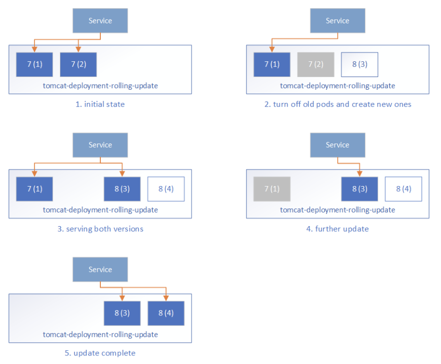
  • Initially, all pods are running Tomcat 7 and the frontend Service routes the traffic to these pods.
  • During the rolling update, Kubernetes takes down some Tomcat 7 pods and creates corresponding new Tomcat 8 pods. It ensures:
    • at most maxUnavailable pods in the desired Pods can be unavailable, that is, at least (replicas – maxUnavailable) pods should be serving the client traffic, which is 2-1=1 in our case.
    • at most maxSurge more pods can be created during the update process, that is 2*50%=1 in our case.
  • One Tomcat 7 pod is taken down, and one Tomcat 8 pod is created. Kubernetes will not route the traffic to any of them because their readiness probe is not yet successful.
  • When the new Tomcat 8 pod is ready as determined by the readiness probe, Kubernetes will start routing the traffic to it. This means during the update process, users may see both the old service and the new service.
  • The rolling update continues by taking down Tomcat 7 pods and creating Tomcat 8 pods, and then routing the traffic to the ready pods.
  • Finally, all pods are on Tomcat 8.

The Rolling Update strategy ensures we always have some Ready backend pods serving client requests, so there’s no service downtime. However, some extra care is required:
– During the update, both the old pods and new pods may serve the requests. Without well defined session affinity in the Service layer, a user may be routed to the new pods and later back to the old pods.
– This also requires you to maintain well-defined forward and backward compatibility for both data and the API, which can be challenging.
– It may take a long time before a pod is ready for traffic after it is started. There may be a long window of time where the traffic is served with less backend pods than usual. Generally, this should not be a problem as we tend to do production upgrades when the service is less busy. But this will also extend the time window for issue 1.
– We cannot do comprehensive tests for the new pods being created. Moving application changes from dev / QA environments to production can represent a persistent risk of breaking existing functionality. The readiness probe can do some work to check readiness, however, it should be a lightweight task that can be run periodically, and not suitable to be used as an entry point to start the complete tests.

Blue/green Deployment

Blue/green deployment quoted from TechTarget

A blue/green deployment is a change management strategy for releasing software code. Blue/green deployments, which may also be referred to as A/B deployments require two identical hardware environments that are configured exactly the same way. While one environment is active and serving end users, the other environment remains idle.

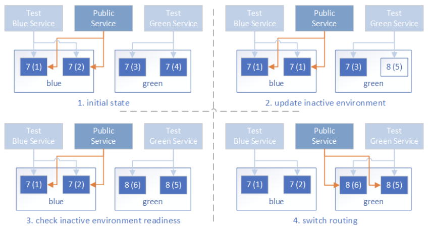
Container technology offers a stand-alone environment to run the desired service, which makes it super easy to create identical environments as required in the blue/green deployment. The loosely coupled Services – ReplicaSets, and the label/selector-based service routing in Kubernetes make it easy to switch between different backend environments. With these techniques, the blue/green deployments in Kubernetes can be done as follows:

  • Before the deployment, the infrastructure is prepared like so:
    • Prepare the blue deployment and green deployment with TOMCAT_VERSION=7 and TARGET_ROLE set to blue or green respectively.

apiVersion: extensions/v1beta1
kind: Deployment
metadata:
name: tomcat-deployment-$
spec:
replicas: 2
template:
metadata:
labels:
app: tomcat
role: $
spec:
containers:
– name: tomcat-container
image: tomcat:$
ports:
– containerPort: 8080
readinessProbe:
httpGet:
path: /
port: 8080

  • Prepare the public service endpoint, which initially routes to one of the backend environments, say TARGET_ROLE=blue.

kind: Service
apiVersion: v1
metadata:
name: tomcat-service
labels:
app: tomcat
role: $
env: prod
spec:
type: LoadBalancer
selector:
app: tomcat
role: $
ports:
– port: 80
targetPort: 8080

  • Optionally, prepare a test endpoint so that we can visit the backend environments for testing. They are similar to the public service endpoint, but they are intended to be accessed internally by the dev/ops team only.

kind: Service
apiVersion: v1
metadata:
name: tomcat-test-$
labels:
app: tomcat
role: test-$
spec:
type: LoadBalancer
selector:
app: tomcat
role: $
ports:
– port: 80
targetPort: 8080

  • Update the application in the inactive environment, say green environment. Set TARGET_ROLE=green and TOMCAT_VERSION=8 in the deployment config to update the green environment.
  • Test the deployment via the tomcat-test-green test endpoint to ensure the green environment is ready to serve client traffic.
  • Switch the frontend Service routing to the green environment by updating the Service config with TARGET_ROLE=green.
  • Run additional tests on the public endpoint to ensure it is working properly.
  • Now the blue environment is idle and we can:
    • leave it with the old application so that we can roll back if there’s issue with the new application
    • update it to make it a hot backup of the active environment
    • reduce its replica count to save the occupied resources

Resources

As compared to Rolling Update, the blue/green up* The public service is either routed to the old applications, or new applications, but never both at the same time.
* The time it takes for the new pods to be ready does not affect the public service quality, as the traffic will only be routed to the new pods when all of them are tested to be ready.
* We can do comprehensive tests on the new environment before it serves any public traffic. Just keep in mind this is in production, and the tests should not pollute live application data.

Jenkins Automation

Jenkins provides easy-to-setup workflow to automate your deployments. With Pipeline support, it is flexible to build the zero-downtime deployment workflow, and visualize the deployment steps.
To facilitate the deployment process for Kubernetes resources, we published the Kubernetes Continuous Deploy and the Azure Container Service plugins built based on the kubernetes-client. You can deploy the resource to Azure Kubernetes Service (AKS) or the general Kubernetes clusters without the need of kubectl, and it supports variable substitution in the resource configuration so you can deploy environment-specific resources to the clusters without updating the resource config.
We created a Jenkins Pipeline to demonstrate the blue/green deployment to AKS. The flow is like the following:

Jenkins Pipeline

  • Pre-clean: clean workspace.
  • SCM: pulling code from the source control management system.
  • Prepare Image: prepare the application docker images and upload them to some Docker repository.
  • Check Env: determine the active and inactive environment, which drives the following deployment.
  • Deploy: deploy the new application resource configuration to the inactive environment. With the Azure Container Service plugin, this can be done with:acsDeploy azureCredentialsId: ‘stored-azure-credentials-id’,
    configFilePaths: “glob/path/to/*/resource-config-*.yml”,
    containerService: “aks-name | AKS”,
    resourceGroupName: “resource-group-name”,
    enableConfigSubstitution: true
  • Verify Staged: verify the deployment to the inactive environment to ensure it is working properly. Again, note this is in the production environment, so be careful not to pollute live application data during tests.
  • Confirm: Optionally, send email notifications for manual user approval to proceed with the actual environment switch.
  • Switch: Switch the frontend service endpoint routing to the inactive environment. This is just another service deployment to the AKS Kubernetes cluster.
  • Verify Prod: verify the frontend service endpoint is working properly with the new environment.
  • Post-clean: do some post clean on the temporary files.

For the Rolling Update strategy, simply deploy the deployment configuration to the Kubernetes cluster, which is a simple, single step.

Put It All Together

We built a quickstart template on Azure to demonstrate how we can do the zero-downtime deployment to AKS (Kubernetes) with Jenkins. Go to Jenkins Blue-Green Deployment on Kubernetes and click the button Deploy to Azure to get the working demo. This template will provision:

  • An AKS cluster, with the following resources:
    • Two similar deployments representing the environments “blue” and “green”. Both are initially set up with the tomcat:7 image.
    • Two test endpoint services (tomcat-test-blue and tomcat-test-green), which are connected to the corresponding deployments, and can be used to test if the deployments are ready for production use.
    • A production service endpoint (tomcat-service) which represents the public endpoint that the users will access. Initially it is routing to the “blue” environment.
  • A Jenkins master running on an Ubuntu 16.04 VM, with the Azure service principal credentials configured. The Jenkins instance has two sample jobs:
    • AKS Kubernetes Rolling Update Deployment pipeline to demonstrate the Rolling Update deployment to AKS.
    • AKS Kubernetes Blue/green Deployment pipeline to demonstrate the blue/green deployment to AKS.
    • We didn’t include the email confirmation step in the quickstart template. To add that, you need to configure the email SMTP server details in the Jenkins system configuration, and then add a Pipeline stage before Switch:stage(‘Confirm’) {
      mail (to: ‘to@example.com’,
      subject: “Job ‘$’ ($) is waiting for input”,
      body: “Please go to $.”)
      input ‘Ready to go?’
      }

      Follow the Steps to setup the resources and you can try it out by start the Jenkins build jobs.

Source

How to setup Rancher 2 in an air gapped environment

Expert Training in Kubernetes and Rancher

Join our free online training sessions to learn how to manage Kubernetes workloads with Rancher.

Sign up here

It’s sometimes not possible to use hosted services like GKE or AKS, and there are occasions where direct internet access is not possibe (offline/airgapped). In these instances it is still possible to use Rancher to manage your clusters.

In this post we’ll walk through what you need to do when you want to run Rancher 2.0 in an offline/air gapped environment.

Private Registry

Everything Rancher related runs in a container, so a place to store the containers in your environment is the first requirement. For this example we will use the Docker Registry. If you already have a registry in place, you can skip these steps.

Note: In Rancher 2.0, only registries without authentication are supported for getting all images needed to get Rancher 2.0 up and running. This does not affect configurable Registries to be used in Workloads.

To run the Docker Registry, you need to run an instance of the registry:2 image. We’ll be exposing the default port (5000), and mount a host directory to make sure we have enough space (we need at least 8GB) and get proper I/O performance.

docker run -d -p 5000:5000 –restart=always –name registry -v /opt/docker-registry:/var/lib/registry registry:2

Making the Rancher images available

When the registry is setup, you can start syncing the needed images to run Rancher 2.0. For this step, we will go through two scenarios:

  • Scenario 1: You have one host that can access DockerHub to pull and save the images, and a separate host that access your private registry to push the images.
  • Scenario 2: You have one host that can access both DockerHub and your private registry.

Scenario 1: One host that can access DockerHub, separate host that can access private registry

In every release (https://github.com/rancher/rancher/releases/tag/v2.0.0), the needed scripts for this scenario are provided. You will need the following:

  • rancher-save-images.sh: This script will pull all needed images from DockerHub, and save all of the images as a compressed file called rancher-images.tar.gz. This file can be transferred to your on-premise host that can access your private registry.
  • rancher-load-images.sh: This script will load images from rancher-images.tar.gz and push them to your private registry. You have to supply the hostname of your private registry as first argument to the script. rancher-load-images.sh registry.yourdomain.com:5000

Flow for scenario 1

Scenario 2: One host that can access both DockerHub and private registry

For this scenario, we provide a file called rancher-images.txt in every release (https://github.com/rancher/rancher/releases/tag/v2.0.0). This file contains every image needed to run Rancher 2.0. This can be tied into any existing automation to sync images you might have, or you can use my scripts/Docker image as shown below

Flow for scenario 2

Configuring Rancher to use the private registry

The last step in the process is to configure Rancher to use the private registry as source to get the images. This can be configured by using the setting system-default-registry in the Settings view.

Settings view

Configuring the setting for use of private registry, do not prefix with https:// or http://

This will make sure that the rancher/rancher-agent container that is used to add nodes to the cluster, will be prefixed with this value. All other images needed will also use this configuration.

If you want to configure the setting when starting the rancher/rancher container, you can use the environment variable CATTLE_SYSTEM_DEFAULT_REGISTRY.

Example:

docker run -d -p 80:80 -p 443:443 -e CATTLE_SYSTEM_DEFAULT_REGISTRY=registry.yourdomain.com:5000 registry.yourdomain.com:5000/rancher/rancher:v2.0.0

Creating a cluster

You can access the Rancher 2.0 UI by using the IP of the host the rancher/rancher container is running on. The initial start-up takes about a minute, and on first access you will be prompted to set a password

Set password

Next, you have to configure the URL that nodes will use to contact this Rancher 2 installation. By default, it will show the IP you are using to visit the UI, but if you are using a DNS name or a loadbalancer, you can change this here.

In the Global view, click Add Cluster

Adding a cluster

For this post, you will be creating a Custom cluster without any advanced options. Please refer to the documentation on configuring advanced options on your cluster.

Adding custom cluster called testcluster

Click Next to create the cluster testcluster.

In the next screen, you get a generated command to launch on your nodes that you want to add to the cluster. The image used in this command should automatically be prefixed with your configured private registry.

Adding nodes to your cluster

You can now select what roles you want to use for the node you want to add, and optionally, you can configure the IP’s used for the node. If not specified, it will auto-detect the IP. Please refer to the documentation on the meaning of the Node Roles.

Configuring access to the registry inside a project

As previously mentioned, at this point Rancher 2 does not support using private registry with authentication for images needed to run Rancher 2.0. It does support this scenario for workloads in projects.

To configure your registry with authentication, you can open your project in a cluster (Default is automatically created for you). When you are in the Default project, you can navigate to Resources -> Registries to configure your registry used for workloads.

Configuring Registries in project Default

Click Add Registry

Adding a registry

Fill in the needed information to access your registry.

Providing credentials for registry

Summary

I hope the information in this how-to was useful, and that you were able to setup Rancher 2.0 in your environment. I know a lot of environments also have a proxy, and we will add or create separate posts for proxy setups soon. Stay tuned.

I will finish by posting a gist with some commands used in this post; hopefully these will be helpful for use or inspiration.

If you have any questions, join our Rancher Users Slack by visiting https://slack.rancher.io and join the #2-0-tech-preview channel. You can also visit our forums to ask any questions you may have: https://forums.rancher.com/

Sebastiaan van Steenis

Sebastiaan is a support engineer at Rancher Labs, helping customers on their journey with containers. You can find him on Rancher Users Slack (https://slack.rancher.io) if you have any questions.

GitHub: superseb

Twitter: @svsteenis

Sebastiaan van Steenis

Sebastiaan van Steenis

Support Engineer

github

Source

Developing on Kubernetes – Kubernetes

Authors: Michael Hausenblas (Red Hat), Ilya Dmitrichenko (Weaveworks)

How do you develop a Kubernetes app? That is, how do you write and test an app that is supposed to run on Kubernetes? This article focuses on the challenges, tools and methods you might want to be aware of to successfully write Kubernetes apps alone or in a team setting.

We’re assuming you are a developer, you have a favorite programming language, editor/IDE, and a testing framework available. The overarching goal is to introduce minimal changes to your current workflow when developing the app for Kubernetes. For example, if you’re a Node.js developer and are used to a hot-reload setup—that is, on save in your editor the running app gets automagically updated—then dealing with containers and container images, with container registries, Kubernetes deployments, triggers, and more can not only be overwhelming but really take all the fun out if it.

In the following, we’ll first discuss the overall development setup, then review tools of the trade, and last but not least do a hands-on walkthrough of three exemplary tools that allow for iterative, local app development against Kubernetes.

Where to run your cluster?

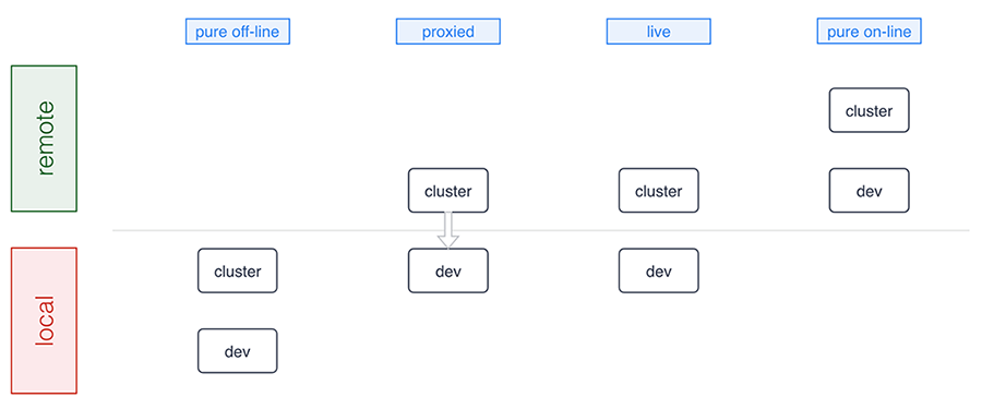
As a developer you want to think about where the Kubernetes cluster you’re developing against runs as well as where the development environment sits. Conceptually there are four development modes:

Dev Modes

A number of tools support pure offline development including Minikube, Docker for Mac/Windows, Minishift, and the ones we discuss in detail below. Sometimes, for example, in a microservices setup where certain microservices already run in the cluster, a proxied setup (forwarding traffic into and from the cluster) is preferable and Telepresence is an example tool in this category. The live mode essentially means you’re building and/or deploying against a remote cluster and, finally, the pure online mode means both your development environment and the cluster are remote, as this is the case with, for example, Eclipse Che or Cloud 9. Let’s now have a closer look at the basics of offline development: running Kubernetes locally.

Minikube is a popular choice for those who prefer to run Kubernetes in a local VM. More recently Docker for Mac and Windows started shipping Kubernetes as an experimental package (in the “edge” channel). Some reasons why you may want to prefer using Minikube over the Docker desktop option are:

  • You already have Minikube installed and running
  • You prefer to wait until Docker ships a stable package
  • You’re a Linux desktop user
  • You are a Windows user who doesn’t have Windows 10 Pro with Hyper-V

Running a local cluster allows folks to work offline and that you don’t have to pay for using cloud resources. Cloud provider costs are often rather affordable and free tiers exists, however some folks prefer to avoid having to approve those costs with their manager as well as potentially incur unexpected costs, for example, when leaving cluster running over the weekend.

Some developers prefer to use a remote Kubernetes cluster, and this is usually to allow for larger compute and storage capacity and also enable collaborative workflows more easily. This means it’s easier for you to pull in a colleague to help with debugging or share access to an app in the team. Additionally, for some developers it can be critical to mirror production environment as closely as possible, especially when it comes down to external cloud services, say, proprietary databases, object stores, message queues, external load balancer, or mail delivery systems.

In summary, there are good reasons for you to develop against a local cluster as well as a remote one. It very much depends on in which phase you are: from early prototyping and/or developing alone to integrating a set of more stable microservices.

Now that you have a basic idea of the options around the runtime environment, let’s move on to how to iteratively develop and deploy your app.

We are now going to review tooling allowing you to develop apps on Kubernetes with the focus on having minimal impact on your existing workflow. We strive to provide an unbiased description including implications of using each of the tools in general terms.

Note that this is a tricky area since even for established technologies such as, for example, JSON vs YAML vs XML or REST vs gRPC vs SOAP a lot depends on your background, your preferences and organizational settings. It’s even harder to compare tooling in the Kubernetes ecosystem as things evolve very rapidly and new tools are announced almost on a weekly basis; during the preparation of this post alone, for example, Gitkube and Watchpod came out. To cover these new tools as well as related, existing tooling such as Weave Flux and OpenShift’s S2I we are planning a follow-up blog post to the one you’re reading.

Draft

Draft aims to help you get started deploying any app to Kubernetes. It is capable of applying heuristics as to what programming language your app is written in and generates a Dockerfile along with a Helm chart. It then runs the build for you and deploys resulting image to the target cluster via the Helm chart. It also allows user to setup port forwarding to localhost very easily.

Implications:

  • User can customise the chart and Dockerfile templates however they like, or even create a custom pack (with Dockerfile, the chart and more) for future use
  • It’s not very simple to guess how just any app is supposed to be built, in some cases user may need to tweak Dockerfile and the Helm chart that Draft generates
  • With Draft version 0.12.0 or older, every time user wants to test a change, they need to wait for Draft to copy the code to the cluster, then run the build, push the image and release updated chart; this can timely, but it results in an image being for every single change made by the user (whether it was committed to git or not)
  • As of Draft version 0.12.0, builds are executed locally
  • User doesn’t have an option to choose something other than Helm for deployment
  • It can watch local changes and trigger deployments, but this feature is not enabled by default
  • It allows developer to use either local or remote Kubernetes cluster
  • Deploying to production is up to the user, Draft authors recommend their other project – Brigade
  • Can be used instead of Skaffold, and along the side of Squash

More info:

Skaffold

Skaffold is a tool that aims to provide portability for CI integrations with different build system, image registry and deployment tools. It is different from Draft, yet somewhat comparable. It has a basic capability for generating manifests, but it’s not a prominent feature. Skaffold is extendible and lets user pick tools for use in each of the steps in building and deploying their app.

Implications:

  • Modular by design
  • Works independently of CI vendor, user doesn’t need Docker or Kubernetes plugin
  • Works without CI as such, i.e. from the developer’s laptop
  • It can watch local changes and trigger deployments
  • It allows developer to use either local or remote Kubernetes cluster
  • It can be used to deploy to production, user can configure how exactly they prefer to do it and provide different kind of pipeline for each target environment
  • Can be used instead of Draft, and along the side with most other tools

More info:

Squash

Squash consists of a debug server that is fully integrated with Kubernetes, and a IDE plugin. It allows you to insert breakpoints and do all the fun stuff you are used to doing when debugging an application using an IDE. It bridges IDE debugging experience with your Kubernetes cluster by allowing you to attach the debugger to a pod running in your Kubernetes cluster.

Implications:

  • Can be used independently of other tools you chose
  • Requires a privileged DaemonSet
  • Integrates with popular IDEs
  • Supports Go, Python, Node.js, Java and gdb
  • User must ensure application binaries inside the container image are compiled with debug symbols
  • Can be used in combination with any other tools described here
  • It can be used with either local or remote Kubernetes cluster

More info:

Telepresence

Telepresence connects containers running on developer’s workstation with a remote Kubernetes cluster using a two-way proxy and emulates in-cluster environment as well as provides access to config maps and secrets. It aims to improve iteration time for container app development by eliminating the need for deploying app to the cluster and leverages local container to abstract network and filesystem interface in order to make it appear as if the app was running in the cluster.

Implications:

  • It can be used independently of other tools you chose
  • Using together with Squash is possible, although Squash would have to be used for pods in the cluster, while conventional/local debugger would need to be used for debugging local container that’s connected to the cluster via Telepresence
  • Telepresence imposes some network latency
  • It provides connectivity via a side-car process – sshuttle, which is based on SSH
  • More intrusive dependency injection mode with LD_PRELOAD/DYLD_INSERT_LIBRARIES is also available
  • It is most commonly used with a remote Kubernetes cluster, but can be used with a local one also

More info:

Ksync

Ksync synchronizes application code (and configuration) between your local machine and the container running in Kubernetes, akin to what oc rsync does in OpenShift. It aims to improve iteration time for app development by eliminating build and deployment steps.

Implications:

  • It bypasses container image build and revision control
  • Compiled language users have to run builds inside the pod (TBC)
  • Two-way sync – remote files are copied to local directory
  • Container is restarted each time remote filesystem is updated
  • No security features – development only
  • Utilizes Syncthing, a Go library for peer-to-peer sync
  • Requires a privileged DaemonSet running in the cluster
  • Node has to use Docker with overlayfs2 – no other CRI implementations are supported at the time of writing

More info:

Hands-on walkthroughs

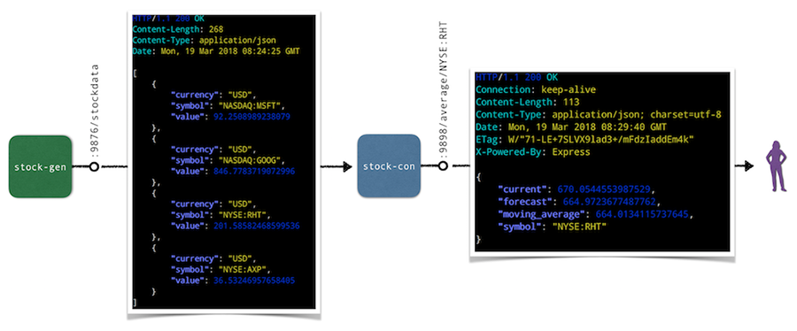
The app we will be using for the hands-on walkthroughs of the tools in the following is a simple stock market simulator, consisting of two microservices:

  • The stock-gen microservice is written in Go and generates stock data randomly and exposes it via HTTP endpoint /stockdata.
    ‎* A second microservice, stock-con is a Node.js app that consumes the stream of stock data from stock-gen and provides an aggregation in form of a moving average via the HTTP endpoint /average/$SYMBOL as well as a health-check endpoint at /healthz.

Overall, the default setup of the app looks as follows:

Default Setup

In the following we’ll do a hands-on walkthrough for a representative selection of tools discussed above: ksync, Minikube with local build, as well as Skaffold. For each of the tools we do the following:

  • Set up the respective tool incl. preparations for the deployment and local consumption of the stock-con microservice.
  • Perform a code update, that is, change the source code of the /healthz endpoint in the stock-con microservice and observe the updates.

Note that for the target Kubernetes cluster we’ve been using Minikube locally, but you can also a remote cluster for ksync and Skaffold if you want to follow along.

Walkthrough: ksync

As a preparation, install ksync and then carry out the following steps to prepare the development setup:

$ mkdir -p $(pwd)/ksync
$ kubectl create namespace dok
$ ksync init -n dok

With the basic setup completed we’re ready to tell ksync’s local client to watch a certain Kubernetes namespace and then we create a spec to define what we want to sync (the directory $(pwd)/ksync locally with /app in the container). Note that target pod is specified via the selector parameter:

$ ksync watch -n dok
$ ksync create -n dok –selector=app=stock-con $(pwd)/ksync /app
$ ksync get -n dok

Now we deploy the stock generator and the stock consumer microservice:

$ kubectl -n=dok apply
-f https://raw.githubusercontent.com/kubernauts/dok-example-us/master/stock-gen/app.yaml
$ kubectl -n=dok apply
-f https://raw.githubusercontent.com/kubernauts/dok-example-us/master/stock-con/app.yaml

Once both deployments are created and the pods are running, we forward the stock-con service for local consumption (in a separate terminal session):

$ kubectl get -n dok po –selector=app=stock-con
-o=custom-columns=:metadata.name –no-headers |
xargs -IPOD kubectl -n dok port-forward POD 9898:9898

With that we should be able to consume the stock-con service from our local machine; we do this by regularly checking the response of the healthz endpoint like so (in a separate terminal session):

$ watch curl localhost:9898/healthz

Now change the code in the ksync/stock-condirectory, for example update the /healthz endpoint code in service.js by adding a field to the JSON response and observe how the pod gets updated and the response of the curl localhost:9898/healthz command changes. Overall you should have something like the following in the end:

Preview

Walkthrough: Minikube with local build

For the following you will need to have Minikube up and running and we will leverage the Minikube-internal Docker daemon for building images, locally. As a preparation, do the following

$ git clone https://github.com/kubernauts/dok-example-us.git && cd dok-example-us
$ eval $(minikube docker-env)
$ kubectl create namespace dok

Now we deploy the stock generator and the stock consumer microservice:

$ kubectl -n=dok apply -f stock-gen/app.yaml
$ kubectl -n=dok apply -f stock-con/app.yaml

Once both deployments are created and the pods are running, we forward the stock-con service for local consumption (in a separate terminal session) and check the response of the healthz endpoint:

$ kubectl get -n dok po –selector=app=stock-con
-o=custom-columns=:metadata.name –no-headers |
xargs -IPOD kubectl -n dok port-forward POD 9898:9898 &
$ watch curl localhost:9898/healthz

Now change the code in the stock-condirectory, for example, update the /healthz endpoint code in service.js by adding a field to the JSON response. Once you’re done with your code update, the last step is to build a new container image and kick off a new deployment like shown below:

$ docker build -t stock-con:dev -f Dockerfile .
$ kubectl -n dok set image deployment/stock-con *=stock-con:dev

Overall you should have something like the following in the end:

Local Preview

Walkthrough: Skaffold

To perform this walkthrough you first need to install Skaffold. Once that is done, you can do the following steps to prepare the development setup:

$ git clone https://github.com/kubernauts/dok-example-us.git && cd dok-example-us
$ kubectl create namespace dok

Now we deploy the stock generator (but not the stock consumer microservice, that is done via Skaffold):

$ kubectl -n=dok apply -f stock-gen/app.yaml

Note that initially we experienced an authentication error when doing skaffold dev and needed to apply a fix as described in Issue 322. Essentially it means changing the content of ~/.docker/config.json to:

{
“auths”: {}
}

Next, we had to patch stock-con/app.yaml slightly to make it work with Skaffold:

Add a namespace field to both the stock-con deployment and the service with the value of dok.
Change the image field of the container spec to quay.io/mhausenblas/stock-con since Skaffold manages the container image tag on the fly.

The resulting app.yaml file stock-con looks as follows:

apiVersion: apps/v1beta1
kind: Deployment
metadata:
labels:
app: stock-con
name: stock-con
namespace: dok
spec:
replicas: 1
template:
metadata:
labels:
app: stock-con
spec:
containers:
– name: stock-con
image: quay.io/mhausenblas/stock-con
env:
– name: DOK_STOCKGEN_HOSTNAME
value: stock-gen
– name: DOK_STOCKGEN_PORT
value: “9999”
ports:
– containerPort: 9898
protocol: TCP
livenessProbe:
initialDelaySeconds: 2
periodSeconds: 5
httpGet:
path: /healthz
port: 9898
readinessProbe:
initialDelaySeconds: 2
periodSeconds: 5
httpGet:
path: /healthz
port: 9898

apiVersion: v1
kind: Service
metadata:
labels:
app: stock-con
name: stock-con
namespace: dok
spec:
type: ClusterIP
ports:
– name: http
port: 80
protocol: TCP
targetPort: 9898
selector:
app: stock-con

The final step before we can start development is to configure Skaffold. So, create a file skaffold.yaml in the stock-con/ directory with the following content:

apiVersion: skaffold/v1alpha2
kind: Config
build:
artifacts:
– imageName: quay.io/mhausenblas/stock-con
workspace: .
docker: {}
local: {}
deploy:
kubectl:
manifests:
– app.yaml

Now we’re ready to kick off the development. For that execute the following in the stock-con/ directory:

$ skaffold dev

Above command triggers a build of the stock-con image and then a deployment. Once the pod of the stock-con deployment is running, we again forward the stock-con service for local consumption (in a separate terminal session) and check the response of the healthz endpoint:

$ kubectl get -n dok po –selector=app=stock-con
-o=custom-columns=:metadata.name –no-headers |
xargs -IPOD kubectl -n dok port-forward POD 9898:9898 &
$ watch curl localhost:9898/healthz

If you now change the code in the stock-condirectory, for example, by updating the /healthz endpoint code in service.js by adding a field to the JSON response, you should see Skaffold noticing the change and create a new image as well as deploy it. The resulting screen would look something like this:

Skaffold Preview

By now you should have a feeling how different tools enable you to develop apps on Kubernetes and if you’re interested to learn more about tools and or methods, check out the following resources:

With that we wrap up this post on how to go about developing apps on Kubernetes, we hope you learned something and if you have feedback and/or want to point out a tool that you found useful, please let us know via Twitter: Ilya and Michael.

Source

Current State of Policy in Kubernetes

Current State of Policy in Kubernetes

Kubernetes has grown dramatically in its impact to the industry; and with rapid growth, we are beginning to see variations across components in how they define and apply policies.

Currently, policy related components could be found in identity services, networking services, storage services, multi-cluster federation, RBAC and many other areas, with different degree of maturity and also different motivations for specific problems. Within each component, some policies are extensible while others are not. The languages used by each project to express intent vary based on the original authors and experience. Driving consistent views of policies across the entire domain is a daunting task.

Adoption of Kubernetes in regulated industries will also drive the need to ensure that a deployed cluster confirms with various legal requirements, such as PCI, HIPPA, or GDPR. Each of these compliance standards enforces a certain level of privacy around user information, data, and isolation.

The core issues with the current Kubernetes policy implementations are identified as follows:

  • Lack of big picture across the platform
  • Lack of coordination and common language among different policy components
  • Lack of consistency for extensible policy creation across the platform.
    • There are areas where policy components are extensible, and there are also areas where strict end-to-end solutions are enforced. No consensus is established on the preference to a extensible and pluggable architecture.
  • Lack of consistent auditability across the Kubernetes architecture of policies which are created, modified, or disabled as well as the actions performed on behalf of the policies which are applied.

Forming Kubernetes Policy WG

We have established a new WG to directly address these issues. We intend to provide an overall architecture that describes both the current policy related implementations as well as future policy related proposals in Kubernetes. Through a collaborative method, we want to present both dev and end user a universal view of policy in Kubernetes.

We are not seeking to redefine and replace existing implementations which have been reached by thorough discussion and consensus. Rather to establish a summarized review of current implementation and addressing gaps to address broad end to end scenarios as defined in our initial design proposal.

Kubernetes Policy WG has been focusing on the design proposal document and using the weekly meeting for discussions among WG members. The design proposal outlines the background and motivation of why we establish the WG, the concrete use cases from which the gaps/requirement analysis is deduced, the overall architecture and the container policy interface proposal.

Key Policy Scenarios in Kubernetes

Among several use cases the workgroup has brainstormed, eventually three major scenario stands out.

The first one is about legislation/regulation compliance which requires the Kubernetes clusters conform to. The compliance scenario takes GDPR as an legislation example and the suggested policy architecture out of the discussion is to have a datapolicy controller responsible for the auditing.

The second scenario is about capacity leasing, or multi-tenant quota in traditional IaaS concept, which deals with when a large enterprise want to delegate the resource control to various Lines Of Business it has, how the Kubernetes cluster should be configured to have a policy driven mechanism to enforce the quota system. The ongoing multi-tenant controller design proposed in the multi-tenancy working group could be an ideal enforcement point for the quota policy controller, which in turn might take a look at kube-arbitrator for inspiration.

The last scenario is about cluster policy which refers to the general security and resource oriented policy control. Luster policy will involve both cluster level and namespace level policy control as well as enforcement, and there is a proposal called Kubernetes Security Profile that is under development by the Policy WG member to provide a PoC for this use case.

Kubernetes Policy Architecture

Building upon the three scenarios, the WG is now working on three concrete proposals together with sig-arch, sig-auth and other related projects. Besides the Kubernetes security profile proposal aiming at the cluster policy use case, we also have the scheduling policy proposal which partially targets the capacity leasing use case and the topology service policy proposal which deals with affinity based upon service requirement and enforcement on routing level.

When these concrete proposals got clearer the WG will be able to provide a high level Kubernetes policy architecture as part of the motivation of the establishment of the Policy WG.

Towards Cloud Native Policy Driven Architecture

Policy is definitely something goes beyond Kubernetes and applied to a broader cloud native context. Our work in the Kubernetes Policy WG will provide the foundation of building a CNCF wide policy architecture, with the integration of Kubernetes and various other cloud native components such as open policy agent, Istio, Envoy, SPIFEE/SPIRE and so forth. The Policy WG has already collaboration with the CNCF SAFE WG (in-forming) team, and will work on more alignments to make sure a community driven cloud native policy architecture design.

Authors: Zhipeng Huang, Torin Sandall, Michael Elder, Erica Von Buelow, Khalid Ahmed, Yisui Hu

Source

How to Deploy Kubernetes Clusters on AWS using RKE

Take a deep dive into Best Practices in Kubernetes Networking

From overlay networking and SSL to ingress controllers and network security policies, we’ve seen many users get hung up on Kubernetes networking challenges. In this video recording, we dive into Kubernetes networking, and discuss best practices for a wide variety of deployment options.

Watch the video

A few months ago, we announced the Rancher Kubernetes Engine (RKE). RKE is a new open source project we have been working on in Rancher to provide a Kubernetes installer that is simple to use, fast and can be used anywhere. You can read more about the project here.

We have been working on adding more functionality and enable more deployment options with each RKE release. One of the most notable features we rolled out recently was initial support for Kubernetes Cloud Providers. In this post, we will do a simple showcase for the AWS cloud provider.

Kubernetes Cloud provider support

Kubernetes provides support for several Core Cloud Providers as well as a simple to implement interface that allows anyone to implement their own cloud provider and link it against the cloud-controller-manager kubernetes component.

Several cloud providers are supported in Kubernetes Core, for example AWS, Azure and GCE.

RKE cloud provider support

While implementing cloud provider support in RKE we will focus mainly on support for the core Kubernetes cloud providers.

Each of the core providers has its own required configuration, limitations, options and features. So, we made a choice at Rancher to roll them out one by one. Starting with version v0.1.3, RKE provides support for the AWS cloud provider. The latest released version, v0.1.5, as of the time of the writing of this article, adds support for Azure as well. To see the latest release of RKE, visit our GitHub release page.

RKE deployment requirements

For the purpose of this how-to article, we will we deploy a minimal cluster on AWS using the simplest configuration possible to show how to use RKE with AWS. This is not a production grade deployment. However, we will provide pointers when possible on how to improve your cluster deployment.

To deploy Kubernetes on AWS, you simply need to:

  • Provision nodes on EC2. For the purpose of this post, we will create a small non-HA cluster with 1 control plane node and 3 worker nodes. If you Like to add HA to your kubernetes cluster, you simply need to add the control plane and etcd roles to 3 or more nodes.
  • The nodes need to have an instance IAM profile that allows kubernetes to talk to AWS API and manage resources. We will look at that shortly.
  • The nodes should be accessible using SSH, and have a supported version of docker installed. If you are not using root, the ssh user you will be using needs to be part of the Docker group.

You will need a linux machine to perform most of the operations in this post. You will also need to install the kubectl command. If you are using MacOS, the process is fairly similar, you just need to download the rke_darwin-amd64 binary instead of the linux one.

Creating an IAM profile

IAM profiles allows for very fine grained controls of access to AWS resources. How you setup and configure the IAM profile will depend on how you design your cluster, what AWS services and resources you are planning to use or planning to allow your applications to use.

You can check IAM profiles provided by kops or by this repo for examples of some fine grained policies.

Also, since your pods will have access to the same resources as your worker node, you should consider using projects like kube2iam.

Step 1: Create an IAM role

Now, first, we create an IAM role and attach our trust policy to it

$ aws iam create-role –role-name rke-role –assume-role-policy-document file://rke-trust-policy.json

The rke-trust-policy.json file will include the following lines:

Step 2: Add our Access Policy

Next, we add our access policy to the role. For the purpose of this post, we will use this simplified and open policy for our instance profile:

$ aws iam put-role-policy –role-name rke-role –policy-name rke-access-policy –policy-document file://rke-access-policy.json

rke-trust-policy.json contains the following:

Step 3: Create the Instance Profile

Finally, we create the instance profile to use with our EC2 instances, and add the role we created to this instance profile:

$ aws iam create-instance-profile –instance-profile-name rke-aws$ aws iam add-role-to-instance-profile –instance-profile-name rke-aws –role-name rke-role

Provisioning Nodes

For this, we will simply use the AWS console launch wizard to create EC2 instances. As we mentioned earlier, we will create 4 instances.

We will go with all defaults, we will choose an Ubuntu 16.04 AMI, and any instance type with sufficient resources to run a basic cluster. The instance type t2.large should be suitable.

When configuring Instance Details, make sure to use the Instance IAM profile we created earlier:

When configuring you instances for a production setup, it’s important to carefully plan and configure your cluster AWS security group rules. For simplicity, we will use an all-open security group in our example.

Node configuration

Now, that we have our 4 instances provisioned, we need to prepare them for installation.

RKE requirements are very simple; all you need is to install docker and add your user to the docker group.

In our case, we will use the latest docker v.1.12.x release, and since we used ubuntu on AWS, our user will be ubuntu. We will need to run the following commands on each instance as root:

## curl releases.rancher.com/install-docker/1.12.sh| bash

## usermod -a -G docker ubuntu

Running RKE

So, this is the fun part. One of RKE design goals was to be as simple as possible. It’s possible to build a kubernetes cluster using only node configurations. The rest of the parameters and configuration options available are automatically set to pre-configured defaults.

We will configure the following cluster.yml file to use our for nodes, and configure Kubernetes with AWS cloud provider:

As of the time of this writing, the latest version of RKE is v0.1.5 Click here for the latest RKE vesion):

$ wget [https://github.com/rancher/rke/releases/download/v0.1.5/rke](https://github.com/rancher/rke/releases/download/v0.1.5/rke)

$ chmod +x rke

Now, let’s save the cluster.yml file in the same directory and build our test cluster:

That’s it. Our cluster should take a few minutes to be deployed. Once the deployment is completed, we can access out cluster using the kubectl command and the generated kube_config_cluster.yml file:

$ export KUBECONFIG=$PWD/kube_config_cluster.yml

NAME STATUS MESSAGE ERROR

scheduler Healthy ok

controller-manager Healthy ok

etcd-0 Healthy {“health”: “true”}

One thing we should point out here: You will notice that the get nodes command is showing private DNS names of the nodes, not the public DNS names we configured in out `cluster.yml.

Even though RKE supports using hostname overrides for configured nodes, it wouldn’t be usable here. This is because Kubernetes uses the cloud provider’s hostnames when configured with a cloud provider and ignores any override values passed.

Using Kubernetes on AWS

Let’s try to take our newly created cluster for a spin!

We will use a slightly modified version of the Kubernetes Guestbook example. We will update this example to achieve two goals:

  • Persist redis master data to an EBS volume.
  • Use an ELB for external access to our application.

Launching a Guestbook

Let’s clone the Kubernetes Examples repo and get to the example files:

$ git clone [https://github.com/kubernetes/examples](https://github.com/kubernetes/examples)

The Guestbook example is a simple php application that writes updates to a redis backend. The redis backend is configured in master and two slave deployments.

It consists of the following manifests which represent kubernetes resources:

  • frontend-deployment.yaml
  • frontend-service.yaml
  • redis-master-deployment.yaml
  • redis-master-service.yaml
  • redis-slave-deployment.yaml
  • redis-slave-service.yaml

We will only modify the ones we need to enable AWS cloud resources.

Using an ELB for frontend

We will update the frontend-service.yaml by adding LoadBalancer type to the service definition:

That’s it! When this service is deployed, Kubernetes will provision an ELB dynamically and point it to the deployment.

Adding persistent storage

We will add a persistent EBS volume to our redis master. We will configure Kubernetes to dynamically provision volumes based on Storage Classes.

First, we will configure the following storage class. Note the we need to set the correct AWS zone as the same one containing the instances we created:

storage-class.yaml:

Next, we will create a PersistentVolumeClaim:

redis-master-pvc.yaml:

And finally, we just need to update the redis-master-deployment.yaml manifest to configure the volume:

Deploying the Guestbook

At this point, we should have a complete set of manifests. The current default Kubernetes version deployed by RKE is v1.8.10-rancher1 . So, I had to update the

Deployment manifests to use apiVersion: apps/v1beta2.

Let’s deploy them to our cluster:

$ kubectl apply -f storage-class.yaml

$ kubectl apply -f redis-pvc.yaml

$ kubectl apply -f redis-master-service.yaml

$ kubectl apply -f redis-master-deployment.yaml

$ kubectl apply -f redis-slave-deployment.yaml

$ kubectl apply -f redis-slave-service.yaml

$ kubectl apply -f frontend-service.yaml

$ kubectl apply -f frontend-deployment.yaml

In a couple of minutes, everything should be up and running.

Examining our deployment

At this point, out guestbook example should be up and running. We can confirm that by running the command:

As you can see, everything is up and running.

Now, let’s try to access our guestbook. We will get the address of the ELB hostname using the following command:

$ kubectl get svc/frontend -o yaml

Using the hostname at the end of the output, you can now access your deployed Guestbook!

Now, let’s run the following command, to see if the PersistentVolume was created for your redis master:

As you can see, a Persistent Volume was dynamically created for our redis master based on the Persistent Volume Claim that we configured.

Recap

In this post we quickly introduced Kubernetes Cloud Provider support and we talked about our plans to support different cloud providers in RKE.

We also described with as much detail as possible how to prepare resources for a simple Kubernetes deployment using the AWS Cloud Provider. And we configured and deployed a sample application using AWS resources.

As we mentioned before, the example in this article is not a production grade deployment. Kubernetes is a complex system that needs a lot of work to be deployed in production, especially in terms of preparing the infrastructure that will host it. However, we hope that we were able to provide a useful example of the available features and pointers on where to go next.

You can find all the files used in the post in this repo: https://github.com/moelsayed/k8s-guestbook

Mohamed el Sayed

Mohamed el Sayed
DevOps Engineer, co-author of RKE

Source

Announcing Kubeflow 0.1 – Kubernetes

Since the initial announcement of Kubeflow at the last KubeCon+CloudNativeCon, we have been both surprised and delighted by the excitement for building great ML stacks for Kubernetes. In just over five months, the Kubeflow project now has:

  • 70+ contributors
  • 20+ contributing organizations
  • 15 repositories
  • 3100+ GitHub stars
  • 700+ commits

and already is among the top 2% of GitHub projects ever.

People are excited to chat about Kubeflow as well! The Kubeflow community has also held meetups, talks and public sessions all around the world with thousands of attendees. With all this help, we’ve started to make substantial in every step of ML, from building your first model all the way to building a production-ready, high-scale deployments. At the end of the day, our mission remains the same: we want to let data scientists and software engineers focus on the things they do well by giving them an easy-to-use, portable and scalable ML stack.

Today, we’re proud to announce the availability of Kubeflow 0.1, which provides a minimal set of packages to begin developing, training and deploying ML. In just a few commands, you can get:

  • Jupyter Hub – for collaborative & interactive training
  • A TensorFlow Training Controller with native distributed training
  • A TensorFlow Serving for hosting
  • Argo for workflows
  • SeldonCore for complex inference and non TF models
  • Ambassador for Reverse Proxy
  • Wiring to make it work on any Kubernetes anywhere

To get started, it’s just as easy as it always has been:

# Create a namespace for kubeflow deployment
NAMESPACE=kubeflow
kubectl create namespace $
VERSION=v0.1.3

# Initialize a ksonnet app. Set the namespace for it’s default environment.
APP_NAME=my-kubeflow
ks init $
cd $
ks env set default –namespace $

# Install Kubeflow components
ks registry add kubeflow github.com/kubeflow/kubeflow/tree/$/kubeflow
ks pkg install kubeflow/core@$
ks pkg install kubeflow/tf-serving@$
ks pkg install kubeflow/tf-job@$

# Create templates for core components
ks generate kubeflow-core kubeflow-core

# Deploy Kubeflow
ks apply default -c kubeflow-core

And thats it! JupyterHub is deployed so we can now use Jupyter to begin developing models. Once we have python code to build our model we can build a docker image and train our model using our TFJob operator by running commands like the following:

ks generate tf-job my-tf-job –name=my-tf-job –image=gcr.io/my/image:latest
ks apply default -c my-tf-job

We could then deploy the model by doing

ks generate tf-serving $ –name=$
ks param set $ modelPath $
ks apply $ -c $

Within just a few commands, data scientists and software engineers can now create even complicated ML solutions and focus on what they do best: answering business critical questions.

It’d be impossible to have gotten where we are without enormous help from everyone in the community. Some specific contributions that we want to highlight include:

It’s difficult to overstate how much the community has helped bring all these projects (and more) to fruition. Just a few of the contributing companies include: Alibaba Cloud, Ant Financial, Caicloud, Canonical, Cisco, Datawire, Dell, Github, Google, Heptio, Huawei, Intel, Microsoft, Momenta, One Convergence, Pachyderm, Project Jupyter, Red Hat, Seldon, Uber and Weaveworks.

If you’d like to try out Kubeflow, we have a number of options for you:

  1. You can use sample walkthroughs hosted on Katacoda
  2. You can follow a guided tutorial with existing models from the examples repository. These include the Github Issue Summarization, MNIST and Reinforcement Learning with Agents.
  3. You can start a cluster on your own and try your own model. Any Kubernetes conformant cluster will support Kubeflow including those from contributors Caicloud, Canonical, Google, Heptio, Mesosphere, Microsoft, IBM, Red Hat/Openshift and Weaveworks.

There were also a number of sessions at KubeCon + CloudNativeCon EU 2018 covering Kubeflow. The links to the talks are here; the associated videos will be posted in the coming days.

Our next major release will be 0.2 coming this summer. In it, we expect to land the following new features:

  • Simplified setup via a bootstrap container
  • Improved accelerator integration
  • Support for more ML frameworks, e.g., Spark ML, XGBoost, sklearn
  • Autoscaled TF Serving
  • Programmatic data transforms, e.g., tf.transform

But the most important feature is the one we haven’t heard yet. Please tell us! Some options for making your voice heard include:

Thank you for all your support so far!
Jeremy Lewi & David Aronchick Google

Source